6
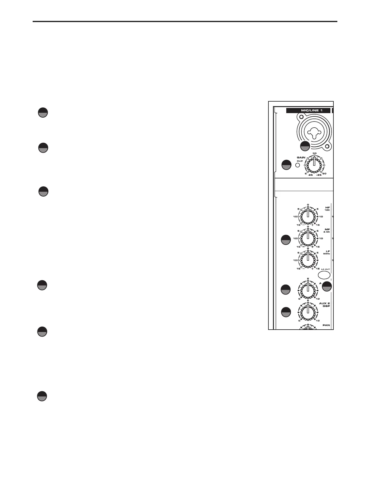
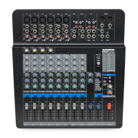
Controls and Functions
MONO INPUT CHANNEL SECTION
The following section details each part of the MDR8’s MONO INPUT CHANNELS including the GAIN control, 3-
BAND EQ, AUX sends, RECORD, PAN and LEVEL controls. The input channels one through four on the MDR8
feature high quality, discrete transistor pre-amp providing transparency and extended dynamic range. The com-
bination connector accepts a standard XLR mic cable for microphone level signals, or a standard 1/4" phone
cable,either balanced (TRS – TIP/ RING/SLEEVE) or unbalanced (TS – TIP/SLEEVE) for line level signals.
GAIN
The MDR8’s pre-amp stage has a variable GAIN control with a range of 5 to
60dB on the MIC input and –26 to +26dB on the LINE input.
CLIP LED
The MDR8’s MIC/LINE pre-amp also includes a CLIP LED which, when illumi-
nated, indicates that the signal is peaking or overloading. To reduce distortion,
lower the GAIN control to keep this LED from staying on.
CHANNEL EQUALIZER
The MDR8 input channels feature a 3-band equalizer allowing you to adjust the
high, mid, and low frequencies independently on each channel. The channel’s
frequency response is flat when the knobs are in the "12:00" position. Rotating
the knob towards the right will boost the corresponding frequency band by
15dB, and rotating it towards the left will cut the frequency by 15dB. The fre-
quency centers, range of boost or cut, and equalizer type for each band are as
follows:
High: 12KHz +/- 15dB shelving type
Mid: 2.5KHz +/- 15dB peaking type
Low: 80Hz +/- 15dB shelving type
LOW CUT FILTER
Each of the MDR8’s channels include a LOW CUT (or high pass) filter which
rolls off the low frequencies from 80Hz and below at the rate of 12dB per
octave.
AUX 1/MON SEND
The MDR8 has two auxiliary sends which can be used for sending signals to the external effects devices or
for creating a monitor mix. The AUX1/MON section is often used for a monitor mix in a live sound mixing, or
for a headphone mix in a recording application. Each input channel includes an AUX 1/Mon send which con-
trols the amount of that channel’s signal that is sent to the AUX 1/Mon bus. The Input channel’s AUX 2/Mon
sends are mixed together and are sent to the AUX 1 OUT jack.
AUX 2 / DSP Send
The MDR8 provides high quality, 24 Bit digital effects, and the level of effects can be set independently on
each channel. The channel’s AUX 2/DSP knob controls the amount of signal that is sent to the AUX
2/DSP bus. The signal of the AUX 2/DSP bus is routed to the internal DSP effects section for onboard sig-
nal processing. The AUX 2/DSP signal can also be sent to an external effect device connected to the
AUX 2 OUT jacks located in the MASTER SECTION jack field.
1
2
4
5
1
2
4
5
6
6
3
3