Do you have a question about the Samson TM300 and is the answer not in the manual?
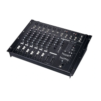
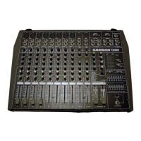
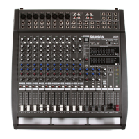
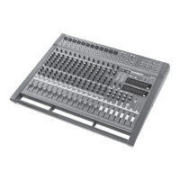
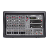
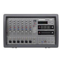
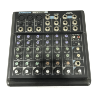
Details the key features of the TM300 mixer, highlighting its compact design and capabilities.
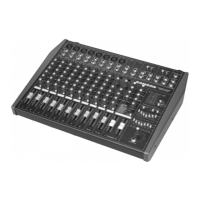
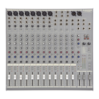
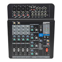
Identifies the channel section of the TM300's front panel, showing input and control layout.
Identifies the main section of the TM300's front panel, including master controls and outputs.
Explains the use of XLR connectors for microphone inputs on the TM300.
Details the use of 1/4" jacks for connecting line-level sources to the TM300.
Describes the use of insert points for external effects processors on channels 1-4.
Explains the function of the Peak LED, indicating overload situations on a channel.
Details the Trim control for adjusting input signal level for each channel.
Explains the 3-band EQ controls for adjusting frequency response on each channel.
Describes the Auxiliary send knobs for routing signals to external devices or internal DSP.
Explains the Pan knob for positioning input signals within the stereo field.
Details the PFL switch for solo monitoring of individual channels via headphones.
Explains the channel fader for controlling signal level sent to the main output and Aux send 2.
Describes the Tape input jacks for connecting tape or CD players.
Details the Aux Returns for connecting external stereo devices and effects processors.
Explains the Record outputs for connecting to a two-track recorder.
Describes the Main Inserts for inserting external effects processors across the main stereo output.
Details the Mono Out for connecting to external monitor mixers or amplifiers.
Explains the Aux Sends for routing signals to external devices or internal DSP.
Details the Tape In Level control for the incoming signal at the Tape Input jacks.
Explains the Record Out Level control for the signal output by the Record Out jacks.
Describes the Auxiliary Return Level knobs for setting input level of stereo auxiliary returns.
Details the Auxiliary Send Level knobs for setting output level of signals routed to auxiliary sends.
Explains the ten-segment bar meter for output or Aux send levels.
Describes the Power LED, indicating when the TM300 is powered on.
Details the Phantom LED, indicating when phantom power is engaged.
Explains the Phantom Power switch for supplying 48 volts to microphone connectors.
Details the Meter/Headphone Source switch for selecting meter/headphone input.
Describes the Rev To Aux 1 Level knob for routing internal DSP signal to Aux Send 1.
Allows selection of three preset reverb effects for the onboard DSP.
Controls routing of internal DSP output to Aux Return 2.
Enables "split mono" configuration for driving main PA and stage monitors.
Activates or deactivates the seven-band graphic master equalizer for left/right sides.
Details the graphic EQ sliders for adjusting seven frequency areas.
Explains the stereo faders for controlling the main left/right stereo outputs.
Details the Headphone Level knob for setting the headphone jack signal level.
Describes the Headphone jack for private monitoring of stereo output, Aux sends, or soloed channels.
Advises to keep the vent unobstructed for proper cooling of the power amplifier.
Describes the fuse holder and its fuse ratings for 115V and 230V operation.
Explains the AC input for connecting the power cable.
Details the speaker outputs for connecting loudspeakers, including impedance and phase.
Describes the power switch for turning the TM300 on and off.
Explains the variable-speed fan for cooling the power amplifier.
Shows how XLR connectors should be wired for mono channel mic-level inputs.
Explains how unbalanced cables use standard 1/4" phone connectors.
Describes how channel and main insert cables should terminate in 1/4" TRS jacks.
Explains the two Aux Sends per channel for routing signals to DSP or external processors.
Details master Aux Send knobs and Aux Returns for mixing effects or external signals.
Identifies the unbalanced 1/4" jacks for connecting Aux Sends to external devices.
Describes the stereo Aux Return jacks for bringing in signals from external effects processors.
Describes channel inserts for affecting individual input signals with external processors.
Describes main inserts for processing the entire mix simultaneously with external gear.
Explains the DSP controls for selecting and managing reverb effects.
| Brand | Samson |
|---|---|
| Model | TM300 |
| Category | Music Mixer |
| Language | English |