4
panel blue LED illumintes indicating
the MediaOne Series is powered up and
ready for operation.
4 AC INLET
- Connect the supplied IEC
power cable here.
5 VOLTAGE SELECTION SWITCH -
This
switch is used to select the amplifiers
operating voltage. NOTE: Bure sure it
is set to the correct voltage for your
country.
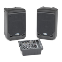
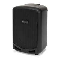
MediaOne Series Layout
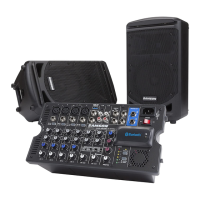
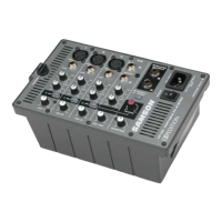
MediaOne Series Rear Panel Layout
1 RCA INPUT – Used to connect signals
from unbalanced, –10dBV devices. The
Red connector is the for Right input and
the White is for the Left input.
2 LEFT SPEAKER OUTPUT
– Push
Terminals for connecting the Left-side
Extension Speaker.
3 POWER SWITCH
– Main power switch.
When set to the ON position, the front
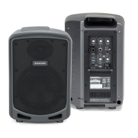
A TERMINAL CUP – Push Terminals for
connecting the Left-side Extension
Speaker.
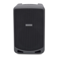
B TUNED PORT - Quiet port design
offering linear extended low
frequency response.
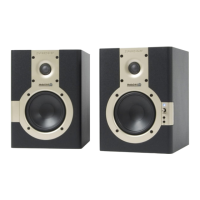
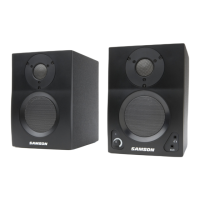
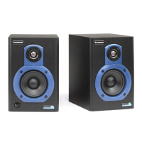
MediaOne 4a and 5a MediaOne 3a
ENGLISH