Guided Tour - Main Section
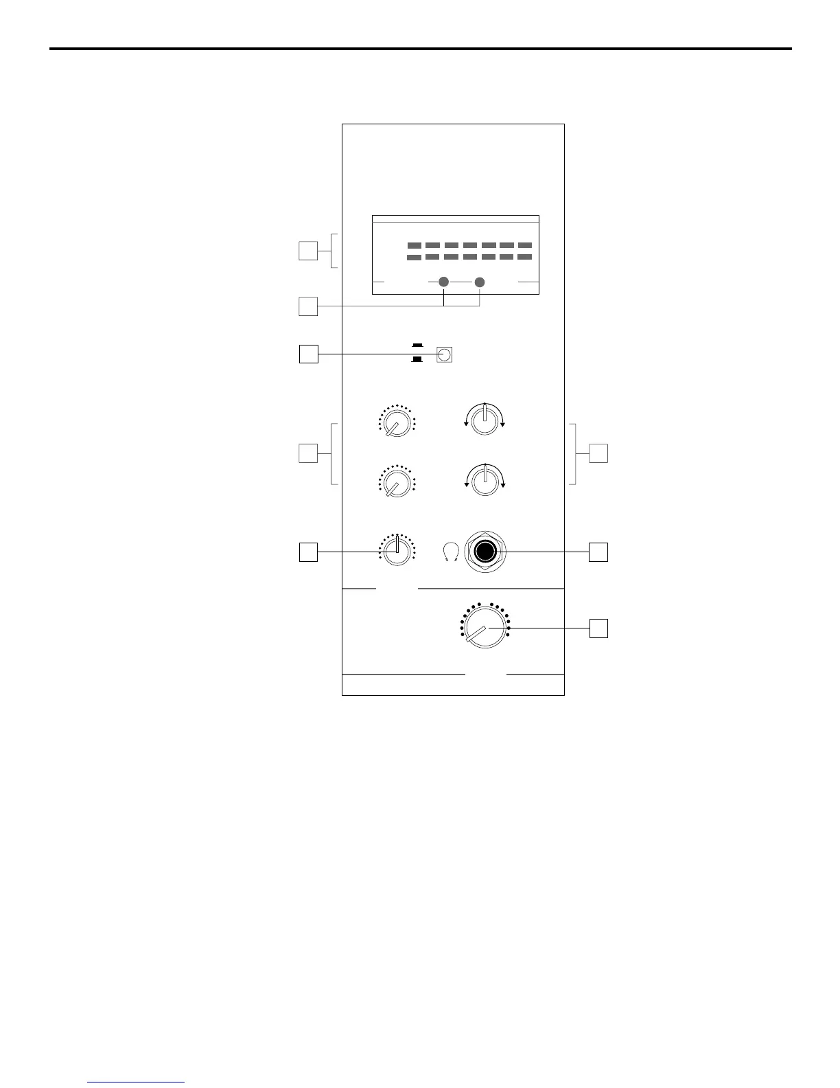
1: Meter - This seven-segment bar meter shows the continuous output level of
the main stereo output. For optimum signal-to-noise ratio, try to adjust all levels
so that program material is usually at or around 0 VU, with occasional but not
steady excursions to the red +2 or +6 segments. See the “Setting the Correct
Gain Structure” section on page 14 for more information.
2: Meter LEDs - These show the status of various conditions within the MPL
1502. The left LED (labeled “Phantom”) lights steadily red when phantom power
is being supplied to all 5 mic inputs (see the “Guided Tour - MPL 1502 Rear
Panel” section on page 8 for more information). The right LED (labeled “Power”)
lights steadily red when the MPL 1502 is powered on.
3: Tape In / Channel 14/15 switch - When pressed in (the “on” position), the
signal arriving at the rear panel tape inputs is automatically routed to stereo
channel 14/15, with the signal connected to the channel 14/15 line inputs
disconnected and the channel 14/15 Trim control made inactive (the tape input
signal is automatically given unity gain). When this switch is out (the “off”
position), channel 14/15 operates normally and the tape input signal is not heard.
6