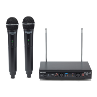
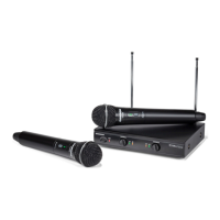
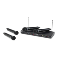
7Stage 212: Dual Handheld Wireless System
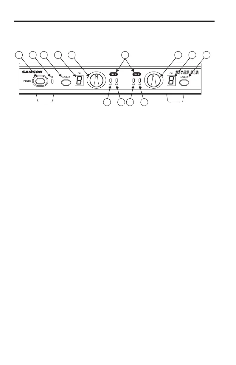
SR212 Receiver Front Panel Features
1. Power Switch - Press to turn the receiver on or off.
2. IR Transmitter - During “IR SET” an infrared light is used to set the transmitter channel.
3. Channel A SELECT Button - Press this button to cycle through Channel A receiver’s operating
channels. Press and hold this button to send the channel information to the transmitter via
infrared transmission.
4. LED Display - The 7-segment LED display shows each receiver’s current operating channel.
The channels are indicated by 1–9 and A–C.
5. VOLUME Control (CH A) - This knob sets the level of the audio signal being output through
the CH A output jacks on the rear panel. Reference level is obtained when the knob is
turned fully clockwise (to its “10” setting).
6. Channel A AF Indicator - Lights green when the corresponding Channel A VH212 transmitter
is powered on, and there is an audio signal present and detected by the receiver. The
indicator lights red when the transmitted audio signal is overloaded.
7. Channel A RF Indicator - Lights orange when the corresponding Channel A VH212
transmitter is powered on, and there is an RF signal present and detected by the receiver.
8. Channel B AF Indicator - Lights green when the corresponding Channel B VH212 transmitter
is powered on, and there is an audio signal present and detected by the receiver. The indi-
cator lights red when the transmitted audio signal is overloaded.
9. Channel B RF Indicator - Lights orange when the corresponding Channel B VH212 transmit-
ter is powered on, and there is an RF signal present and detected by the receiver.
10. Volume Control (Channel B) - This knob sets the level of the audio signal being output
through the CH A output jacks on the rear panel. Reference level is obtained when the
knob is turned fully clockwise (to its “10” setting).
11. LED Display - The 7-segment LED display shows each receiver’s current operating channel.
The channels are indicated by 1–9 and A–C.
12. Channel B SELECT Button - Press this button to cycle through Channel B receiver’s operating
channels. Press and hold this button to send the channel information to the transmitter via
infrared transmission.
13. Channel Label - The channel label designates the frequency group. The label color matches
the label color of the corresponding handheld microphone transmitter.
1 2 3 4 5
76 98
12111013