Do you have a question about the Samson Stage 55 and is the answer not in the manual?
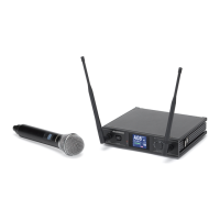
Antenna mountings allow full rotation for optimum placement.
Sets the level of the audio signal being output.
Displays the strength of the incoming audio signal.
Determines the maximum range before audio signal dropout.
Indicate which antenna is currently receiving the strongest signal.
Displays the strength of the incoming radio signal.
Turns the SR55 receiver power on and off.
Connects the supplied 12-volt power adapter.
XLR jack for connecting to professional audio equipment.
Sets the audio output level attenuation of the balanced output.
1/4" jack for connecting to consumer audio equipment.
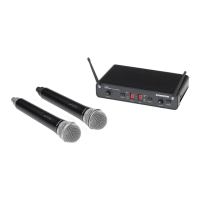
Antenna mounting allows full rotation for optimum placement.
Sets the level of the audio signal being output.
Displays the strength of the incoming audio signal.
Determines the maximum range before audio signal dropout.
Lights when carrier signal of sufficient strength is received.
Displays the strength of the incoming radio signal.
Turns the SR5 receiver power on and off.
Connects the supplied 12-volt power adapter.
XLR jack for connecting to professional audio equipment.
Sets the audio output level attenuation of the balanced output.
1/4" jack for connecting to consumer audio equipment.
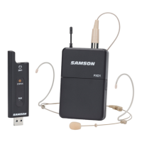
Connects lavaliere, headset, or instrument cable.
Indicates battery strength (red, yellow, green).
Mutes audio signal transmission.
Accesses power switch and gain control.
Turns the ST5 transmitter on or off.
Selects input level (0dB or -15dB).
Adjusts input gain sensitivity.
Holds a standard 9-volt alkaline battery.
Used for gain and squelch adjustments.
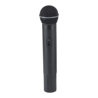
Mutes audio signal transmission.
Shows battery status (red, yellow, green).
Turns the HT5 transmitter on or off.
Adjusts input sensitivity.
Holds a standard 9-volt alkaline battery.
Ensure matching channels for correct operation.
Position receiver for line-of-sight and vertical antennas.
Ensure transmitter is off before setup.
Install battery and close compartment.
Connect receiver output to amplifier/mixer.
Turn on receiver, then transmitter.
Adjust levels using meters and gain controls for optimal signal.
Check output levels and gain structure to resolve distortion.
Adjust gain and microphone position for clear audio.
Set for optimal noise reduction without signal dropout.
Test system coverage in the performance area.
| Brand | Samson |
|---|---|
| Model | Stage 55 |
| Category | Microphone system |
| Language | English |