Studio GT Owner’s Manual 4
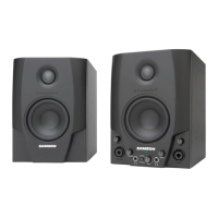
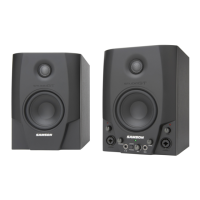
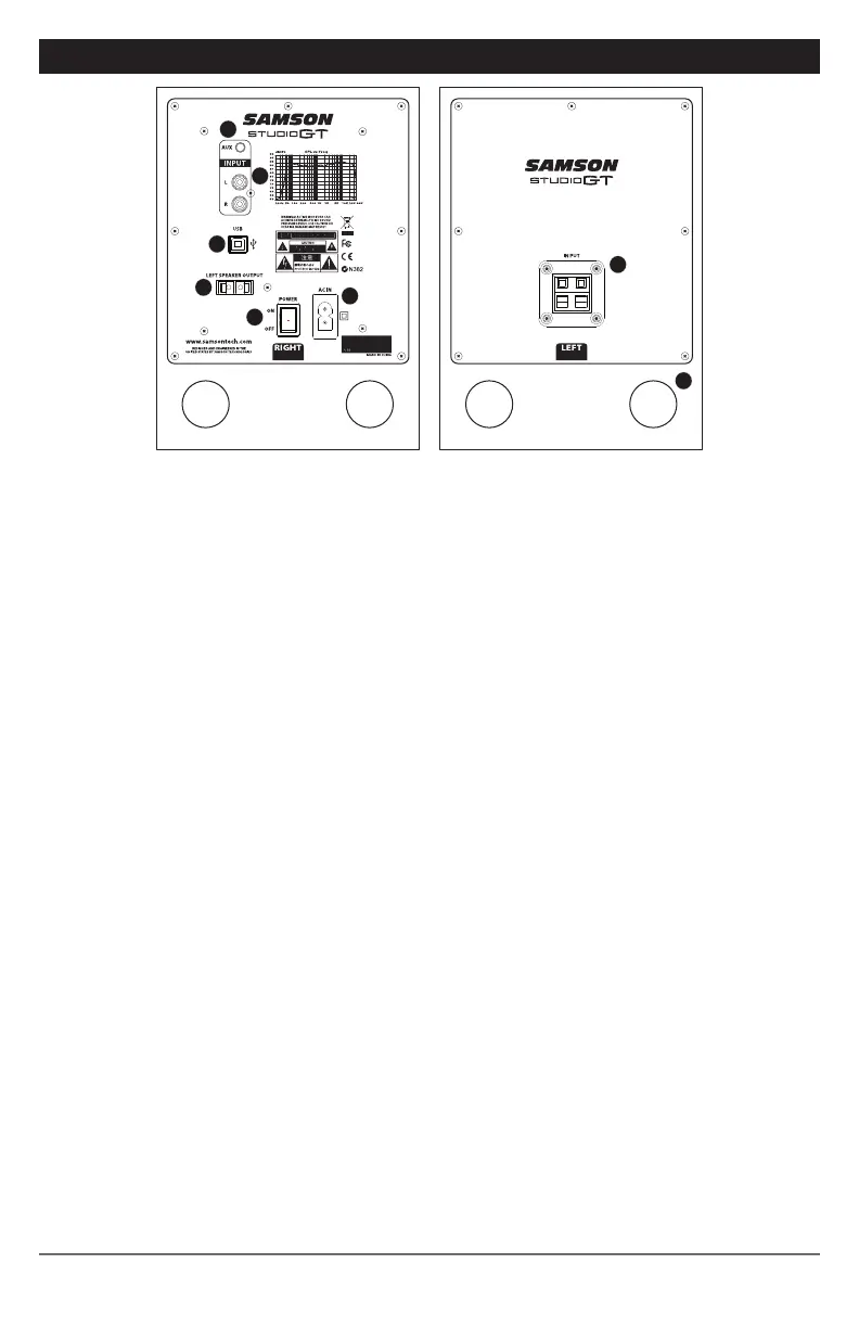
STUDIO GT REAR PANEL LAYOUT
1. 1/8” AUX INPUT – 3.5mm stereo input jack for connecting a second line level signal
source, like an MP3 player. This input is not sent through the USB output.
2. RCA INPUT – Used to connect signals from unbalanced, –10dBV devices, like a
mixer. The Red connector is for the Right input and the White is for the Left input.
3. USB Connector – Connect the supplied USB cable to this rear panel USB “B”
connector.
4. LEFT SPEAKER OUTPUT – Push Terminals for connecting the Left-side Extension
Speaker.
5. POWER SWITCH – Main power switch. When set to the ON position, the front
panel green LED illuminates indicating the Studio GT is powered up and ready for
operation.
6. AC INLET - Connect the supplied IEC power cable here.
7. TERMINAL CUP – Push Terminals for connecting the Left-side Extension Speaker to
the Active (Right-side) speaker.
8. TUNED PORT - Quiet port design offering linear extended low frequency response.
4
3
1
2
5
6
7
8