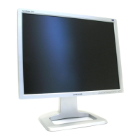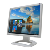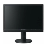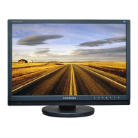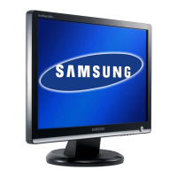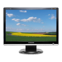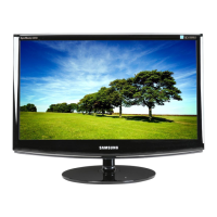
Do you have a question about the Samsung 214T and is the answer not in the manual?
Covers warnings, servicing, and fire/shock hazards for safe operation.
Guidelines for safe servicing, including handling components and insulation checks.
Procedures to prevent damage from static electricity when handling sensitive components.
Safety measures during product installation, ventilation, and cable management.
Details on features like Magic Color Pro, Magic Bright, and Auto Pivot.
Technical details including panel type, resolution, scanning frequency, and power consumption.
Compares key specifications between LS21BRBS and LS20BRCS models.
Lists optional accessories and their associated part numbers.
Lists necessary equipment and steps for automatic color and EDID data input.
Procedures for adjusting OSD settings after panel or lamp replacement.
Guides on displaying and controlling the service function OSD menu for diagnostics.
Step-by-step guide for installing EDID data using a Windows program after main board replacement.
Troubleshooting flowchart for diagnosing and resolving a lack of power.
Diagnostic steps for troubleshooting analog video signal issues.
Diagnostic steps for troubleshooting digital video signal issues.
Troubleshooting flow for problems with video signal input.
Shows connections for analog, digital, AV, and S-Video inputs.
Details the main processor and memory interfaces.
Illustrates power distribution and interface connections.
Depicts the video decoder and related circuits.
Shows power management and control signal circuits.
Illustrates the microcontroller and communication interfaces.
Explains the function of each button on the monitor's front panel.
Describes power switch, power input, and rear connectors for various inputs.
Instructions for pivot and height adjustment of the monitor stand.
Procedures for removing the monitor stand and attaching a VESA mount.
Step-by-step guide for safely taking the monitor apart.
Guidelines for reassembling the monitor in reverse order of disassembly.
Identifies major components on the main PCB and their locations.
Explains the operational roles of key ICs and blocks like Scaler, MICOM, and Video Decoder.
Definitions of key terms like TFT-LCD, ADC, PLL, SMPS, and DVI.
Instructions for connecting the monitor to a computer, including D-Sub and DVI options.
Guide for connecting AV devices (VCR, DVD) and digital DVD players.
Details pin configurations for D-Sub and DVI connectors.
Provides timing parameters for various computer-generated video signals.
Lists supported display modes and their corresponding timing parameters.
Lists different panel models, their codes, and associated features.
