Samsung Electronics 7-1
7. Reference Sheet
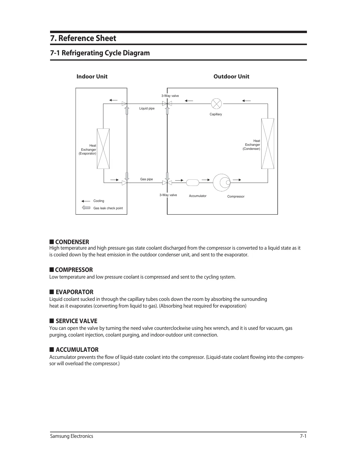
7-1 Refrigerating Cycle Diagram
Indoor Unit Outdoor Unit
Heat
Exchanger
(Evaporator)
Heat
Exchanger
(Condenser)
Cooling
Gas leak check point
Liquid pipe
Gas pipe
Compressor
Accumulator
3-Way valve
Capillary
3-Way valve
Q CONDENSER
High temperature and high pressure gas state coolant discharged from the compressor is converted to a liquid state as it
is cooled down by the heat emission in the outdoor condenser unit, and sent to the evaporator.
Q COMPRESSOR
Low temperature and low pressure coolant is compressed and sent to the cycling system.
QEVAPORATOR
Liquid coolant sucked in through the capillary tubes cools down the room by absorbing the surrounding
heat as it evaporates (converting from liquid to gas). (Absorbing heat required for evaporation)
QSERVICE VALVE
You can open the valve by turning the need valve counterclockwise using hex wrench, and it is used for vacuum, gas
purging, coolant injection, coolant purging, and indoor-outdoor unit connection.
QACCUMULATOR
Accumulator prevents the flow of liquid-state coolant into the compressor. (Liquid-state coolant flowing into the compres-
sor will overload the compressor.)
 Loading...