Do you have a question about the Samsung AF28FVSDA N Series and is the answer not in the manual?
Guidelines for service personnel regarding repairs and handling.
Warnings about static electricity and product handling.
General safety guidelines for product operation and maintenance.
Additional precautions and important notes not covered elsewhere.
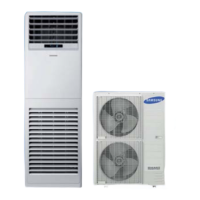
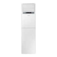
Overview of product features, functions, and capabilities.
Detailed technical specifications, performance data, and dimensions.
Details on optional accessories and their specifications.
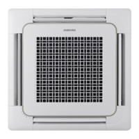
Step-by-step procedures for safely disassembling the indoor unit.
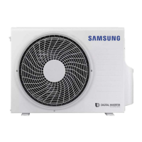
Step-by-step procedures for safely disassembling the outdoor unit.
Guide for configuring Printed Circuit Board (PBA) options for the unit.
Explanation of error codes displayed by the unit and their meanings.
Checklist of initial items to verify before proceeding with troubleshooting.
Detailed troubleshooting steps for common operational issues and error codes.
Visual diagrams of the Printed Circuit Board (PCB) layouts.
Layout diagram of the main PCB for the indoor unit.
Layout diagram of the main control PCB.
Layout diagram of the PCB for the unit's display interface.
Layout diagram of the PCB for the unit's power supply.
Layout diagram of the sub PCB for touch control functions.
Layout diagram of the sub PCB for the unit's lighting components.
Layout diagram of the sub PCB for network and communication modules.
Layout diagram of the main PCB for the outdoor unit.
Wiring diagram specific to models other than KFR-50LW/EMA1.
Wiring diagram specifically for the KFR-50LW/EMA1 model.
Guide to understanding and decoding product model name conventions.
Diagram illustrating the unit's refrigerant cycle and components.
Graph displaying pressure values based on operating temperatures.
Graph showing resistance values for specific components.
| Brand | Samsung |
|---|---|
| Model | AF28FVSDA N Series |
| Category | Air Conditioner |
| Language | English |