This document is a service manual for Samsung System Air Conditioner Fan Coil Units, covering various models including 1-Way Cassette, 4-Way Cassette, and Circular Cassette types. The manual provides comprehensive information for service, maintenance, and troubleshooting of these units.
Function Description:
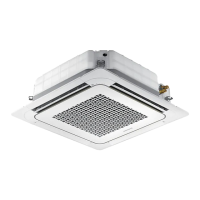
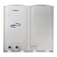
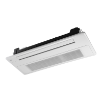
The Samsung Fan Coil Unit is an indoor air conditioning component designed to circulate and condition air within a space. It typically works in conjunction with an outdoor unit (not detailed in this manual) to provide cooling and heating. The units come in different configurations, including slim 1-way cassette, 4-way cassette (small/medium/large), and 360 circular cassette types, to suit various installation requirements and aesthetic preferences. These units are equipped with fan motors, heat exchangers, and control PCBs to manage air flow, temperature, and system operation. Some models feature Wind Free technology, which aims to provide a comfortable environment by minimizing direct airflow.
Important Technical Specifications:
The manual provides detailed specifications for various models, categorized by cassette type and capacity. Key specifications include:
- Power Supply: Typically 1, 220-240V, 50/60Hz for most models, with some variations.
- Cooling Capacity (Nominal): Ranges from 2.60 kW (AG026MN1DEH/EU) to 10.5 kW (AG105MN4DKH/EU, AG105MN4PKH/EU).
- Heating Capacity (Nominal): Ranges from 2.90 kW (AG026MN1DEH/EU) to 10.7 kW (AG105MN4DKH/EU, AG105MN4PKH/EU).
- Power Input (Nominal): For cooling, ranges from 27.0 W to 110 W; for heating, ranges from 27.0 W to 110 W.
- Current Input (Nominal): For cooling, ranges from 0.14 A to 0.5 A; for heating, ranges from 0.14 A to 0.5 A.
- Heat Exchanger: Fin & Tube type, with Aluminum fins and Copper tubes. Fin surface treatment is typically "Green water-friendly."
- Fan Motor: DC type, with output ranging from 27 W to 97 W, and a cross-flow or turbo fan type depending on the model. Air flow rates are provided in CMM (Cubic Meters per Minute) or H/M/L (UL) (High/Medium/Low).
- Water Flow Rate (Cooling/Heating): Ranges from 7.5 LPM to 28.9 LPM, with corresponding pressure drops in kPa.
- Water Pipe Connections: Inlet and outlet types are PF Male, typically 20A (3/4") or 25A (1"). Insulation is provided for both inlet/outlet pipes.
- Drain Pipe: VP20 (OD26, ID20) or VP25 (OD32, ID25).
- Communication Cable: Min thickness 0.75 mm2, F1, F2 remarks.
- Dimensions (Net): Varies significantly by model, e.g., 970 x 135 x 410 mm for slim 1-way cassette (AG026MN1DEH/EU) to 1410 x 23/35 x 500 mm for 4-way cassette panels.
- Weight (Net): Ranges from 10.1 kg to 25 kg for the main unit, and 3.6 kg to 8.4 kg for the panel.
- Case Material: Plastic.
- Sound Pressure/Power: Specified in dB(A) for high, mid, and low settings, varying by model and operation mode (cooling).
Usage Features:
The units are designed for various indoor applications, offering different panel types (normal, interior, Wind Free, buried, exposed) and communication options (S-NET CLOUD, BACnet G/W, external contact interface, ON/OFF controller, touch central controller, FCU interface, power monitoring interface, SIM interface, PIM interface, wireless remote controller, wired remote controller, S-NET converter, WIFI-KIT). The manual details how to set fan coil unit addresses and installation options using a remote controller, including procedures for entering option setting mode and adjusting various parameters like fan mode, heating mode, dry mode, and auto mode. The option codes are model-specific, allowing for tailored configurations to suit different installation site conditions.
Maintenance Features:
The manual provides detailed instructions for disassembly and reassembly of various components, crucial for maintenance and repair. These include:
- Panel and Filter Removal: Step-by-step guides for accessing internal components.
- Drain Pan Removal: Instructions for removing the drain pan, with a caution to avoid touching the heat exchanger board.
- Electronics Board Removal: Procedures for safely disconnecting and removing the PCB.
- Heat Exchanger Removal: Detailed steps, including a critical caution about opening the air release valve to prevent performance degradation and noise during reassembly.
- Fan and Motor Removal: Instructions for disassembling the fan and motor assembly.
- SPI Kit Removal: Steps for removing the SPI kit.
- Sensor Removal: Procedures for detaching temperature sensors (room, EVAP IN, EVAP OUT).
- Troubleshooting: A comprehensive section dedicated to diagnosing and resolving common errors. This includes:
- LED Display Codes: Interpretation of flickering LED patterns for various error conditions (e.g., sensor errors, communication errors, EEPROM errors, fan operation errors).
- Number Expression Method: How error numbers are displayed on cable remote controls.
- Fan Coil Unit Related Error Codes: A table listing error codes, their causes, and explanations (e.g., repeated address setting, sensor errors, communication errors, EEV errors, Fahrenheit/Celsius confusion).
- Appropriate Measures for Different Symptoms: Flowcharts and diagnostic steps for specific errors like ROOM sensor error, EVAP IN/OUT sensor errors, water temperature increase prevention error, floating switch detection error, fan operation error, EEPROM error, and remote control option error. These steps often involve checking sensor resistance, verifying connections, and replacing faulty PCBs.
- Reference Sheet: Provides an index for model names, breaking down the model code into product classification, feature, detailed classification, power specifications, product type, and panel version. This helps in identifying the specific characteristics of each unit.
The manual emphasizes safety precautions for service personnel, including using standard parts, preventing static electricity discharge, and ensuring power is disconnected before working on electrical components. It also highlights the importance of proper reassembly to avoid issues like noise or reduced performance.