EasyManua.ls Logo

Samsung AG042KSVANH User Manual

Samsung AG042KSVANH
142 pages
To Next Page IconTo Next Page
Page #1 background imageLoading...
Page #1 background image
1. Precautions
2. Product Features and Specifications
3. Disassembly and Reassembly
4. Troubleshooting
5. PCB Diagram and Parts List
6. Wiring Diagram
7. Cycle Diagram
8. Key Options
9. Trial Operation
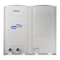
CONTENTSDVM CHILLER
DVM CHILLER
AG042KSVANH/AG056KSVANH/AG070KSVANH
AG042KSVGNH/AG056KSVGNH/AG070KSVGNH
SYSTEM AIR CONDITIONER

Table of Contents

Other manuals for Samsung AG042KSVANH

Questions and Answers:

Samsung AG042KSVANH Specifications

General IconGeneral
BrandSamsung
ModelAG042KSVANH
CategoryAir Conditioner
LanguageEnglish

Summary

Precautions

Precautions for the Service

Guidelines for performing service and repairs on electrical parts and connections.

Precautions for Static Electricity and PL

Safe handling of PCB power terminals to prevent damage from static discharge.

Safety Precautions

General safety rules regarding electrical connections, grounding, and product security.

Refrigerant Handling Precautions

Safety measures and environmental considerations for handling refrigerant during DVM CHILLER operations.

Welding Precautions

Safety procedures and material removal requirements before welding DVM CHILLER pipes.

Product Features and Specifications

Product Features

Highlights key advantages and technological aspects of the DVM CHILLER, including DSI System and inverter technology.

Changes in comparison to DVM S

Details modifications and improvements made in the DVM CHILLER compared to the previous DVM S model.

Product Structure

Illustrates the internal components and layout of the DVM CHILLER for both Hydro and Inverter control sides.

Product Specifications

Provides detailed technical specifications for various models, including performance, electrical, and dimensional data.

Disassembly and Reassembly

Necessary Tools

Lists the essential tools required for performing disassembly and reassembly procedures on the unit.

Disassembly and Reassembly Procedures

Step-by-step instructions for disassembling and reassembling main parts of the AG042/056/070KSV model.

Service Work on Main Parts

Detailed procedures for servicing key components like the water pump, sensors, and heat exchanger.

Troubleshooting

Check-up Window Description

Explains the functions and indicators displayed on the unit's check-up window for diagnostics.

Service Operation Modes

Details various special operation modes accessible via tact switches for service and maintenance tasks.

EEPROM Code Table and Option Codes

Provides tables for DVM Chiller EEPROM codes and option code classification by model.

Error Number Display Method

Describes how integrated error codes are displayed, including integrated error code structure and display examples.

Appropriate Measures for Symptoms

Offers troubleshooting guidance and corrective actions for a wide range of specific error codes and symptoms.

PCB Diagram and Parts List

ASSY PCB MAIN-HYDRO

Detailed diagram and pinout for the Main Hydro PCB, listing all connector functions and specifications.

ASSY PCB MAIN

Diagram and pinout for the Main PCB, illustrating connector locations and their respective signal assignments.

ASSY PCB SUB-EMI (PF#8 H power model)

Diagram and pinout for the SUB-EMI PCB (PF#8), showing power input and fan connections.

ASSY PCB SUB-EMI (PF #9 H power model)

Diagram and pinout for the SUB-EMI PCB (PF#9), detailing power input and various signal connections.

ASSY PCB MAIN-HUB

Diagram and pinout for the Main Hub PCB, showing various sensor and communication connections.

ASSY PCB INVERTER (PF #8)

Diagram and pinout for the Inverter PCB (PF#8), illustrating power, communication, and sensor connections.

ASSY PCB INVERTER (PF #9)

Diagram and pinout for the Inverter PCB (PF#9), detailing power, communication, and sensor connections.

ASSY PCB SUB-COMM

Diagram and pinout for the SUB-COMM PCB, showing various input and output signal connections.

Wiring Diagram

DVM CHILLER Hydro Part Wiring Diagram

Schematic illustrating the wiring connections for the Hydro part of the DVM CHILLER, including all components and terminals.

DVM CHILLER Inverter Control Part Wiring Diagram

Schematic showing the wiring for the Inverter control part of the DVM CHILLER, detailing connections for various PCBs and components.

Cycle Diagram

Cycle Diagram

Illustrates the refrigerant cycle and component flow within the DVM CHILLER system, with an abbreviation key.

Key Options

Setting Hydro Controller Option

Guide on how to set various operational options for the Hydro controller using tact switches and display menus.

How to Set Hydro Controller Option

Detailed steps and explanations for configuring hydro controller options, including factory defaults and definitions.

Water Law Function

Explanation of the Water Law function, which adjusts water outlet temperature based on load and ambient conditions for efficiency.

MICOM Version Display

Instructions on how to display MICOM versions for various unit components and check their settings.

Setting Inverter Controller Option

Guide on setting inverter controller options using tact switches, including initial display and operational parameters.

Special Operation Settings

Instructions for setting special operations via tact switches, including emergency functions and compressor malfunction settings.

Related product manuals