K
Karen ReynoldsJul 25, 2025
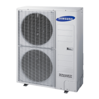
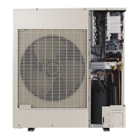
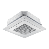
Why does my Samsung AM048FNHDCH/AA show a communication error between indoor and outdoor units?
- EEmily FieldsJul 25, 2025
This error occurs due to several reasons: 1. There is no communication between the indoor and outdoor units for 2 minutes. 2. A communication error was received from the outdoor unit. 3. There is a 3-minute tracking error on the outdoor unit. 4. A communication error occurred after tracking due to an unmatching number of installed units. 5. An error is due to a repeated communication address. 6. The communication address is not confirmed, or another outdoor unit communication error not listed above occurred. The error codes associated with these issues are E101, E102, E202, E201, E108 and E109.