Do you have a question about the Samsung AM048TXMDCH and is the answer not in the manual?
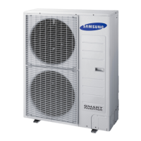
Details on the outdoor unit's features, including fan motor, heat exchanger, and compressor.
Table detailing performance, power, compressor, refrigerant, fan, and pipe specifications.
Lists the essential tools required for performing disassembly and reassembly procedures.
Information on how errors are displayed on the outdoor unit's error display.
Comprehensive list of error codes and their corresponding explanations for system faults.
Step-by-step guides to diagnose and resolve specific operational symptoms and errors.
Detailed layout and numbering of components on the outdoor unit's main PCB.
Diagram showing the layout and components of the 1-phase outdoor unit inverter PCB.
Diagram illustrating the components and connections of the 1-phase outdoor unit EMI PCB.
Schematic illustrating the electrical connections for the 1-phase system.
Visual representation of the refrigerant flow and components in the outdoor unit.
Explanation of the coding system used to identify model variations and features.
Steps and procedures for performing a system check operation and interpreting results.
Guide on how to use the function to detect and evaluate refrigerant levels in the system.
| Brand | Samsung |
|---|---|
| Model | AM048TXMDCH |
| Category | Air Conditioner |
| Language | English |