Outdoor unit
6. Electrical Wiring Diagrams
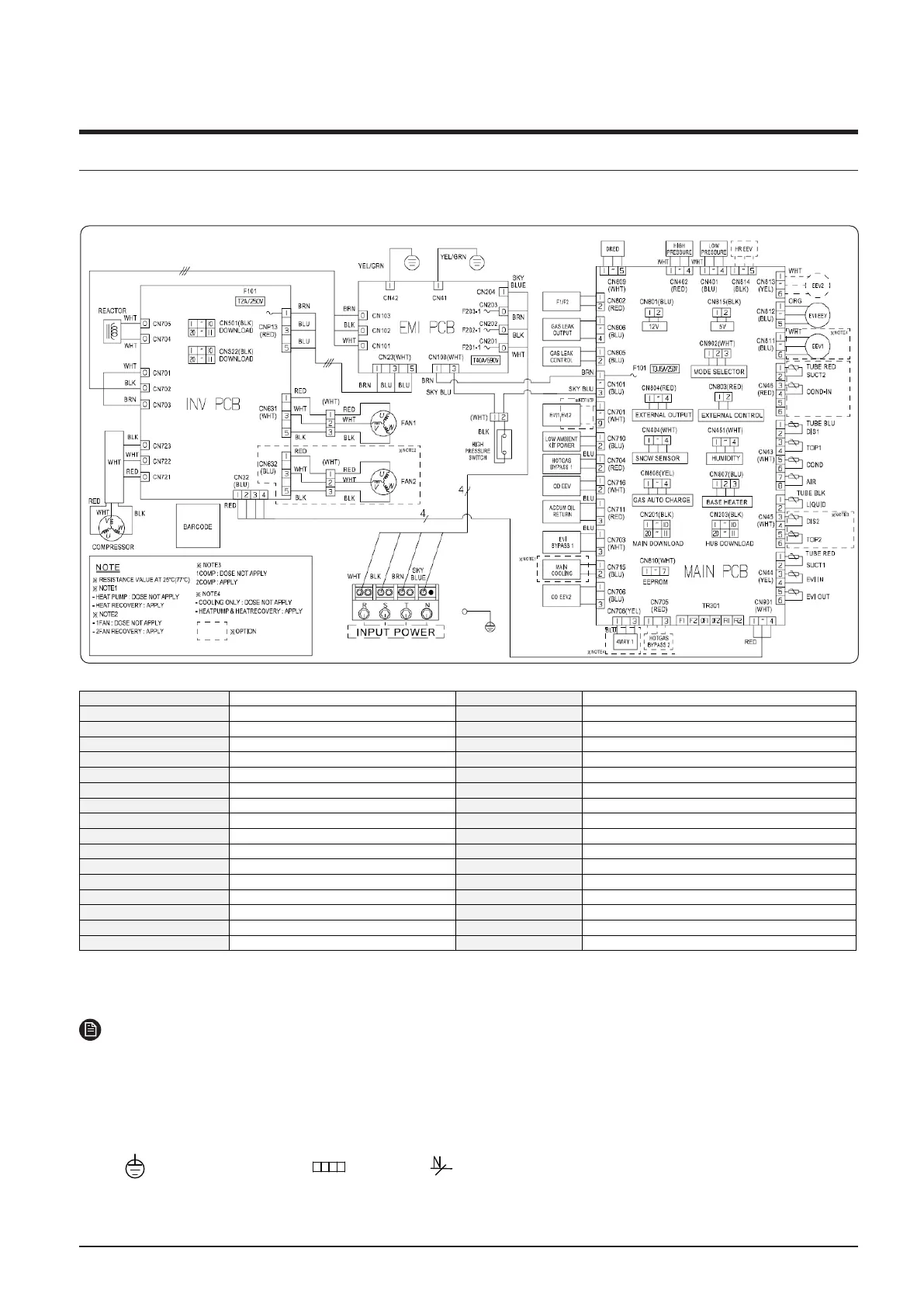
AM100~120AXVDGH/EU
NOTE
• This wiring diagram applies only to the outdoor unit.
• Colors blk: black, red: red, blu: blue, wht: white, yel: yellow, brn: brown, sky: skyblue
• When operating, don’t shortcircuit the protection device (High Pressure switch)
• For connection wiring indoor-outdoor transmission F1-F2, outdoor_outdoor transmission OF1-OF2, refer to
the installation manual.
• Protective earth(screw),
: connector, : The wire quantity
I
NV PCB
Printed circu
it board (inverter)
EVI-OUT(10K) Thermistor (EVI-out_10kohm)
EMI PCB Printed circu
it board (emi)
EVI-IN(10K) Thermistor (EVI-in_10kohm)
M
AIN PCB
Printed circu
it board (main)
SUCT1(10K) Thermistor (Suction Temp.1_10Kohm)
COMPRESSOR M
otor (compressor)
SUCT2(10K) Thermistor (Suction Temp.2_10Kohm)
FAN1 M
otor (fan1)
SNOW SENSOR SNOW SENSOR
EVI V/V1 Solenod
e valve (EVI1)
AI
R(10K)
Thermistor (Ambient Temp._10Kohm)
EVI V/V2 Solenod
e valve (EVI2)
COND(10K) Thermistor (Cond Out Temp._10Kohm)
EVI EEV Electronic expansion va
lve (EVI)
TOP1(200K) Thermistor (Compressor Top 1_200Kohm)
EEV1 Electronic expansion va
lve 1
TOP2(200K) Thermistor (Compressor Top 2_200Kohm)
EEV2 Electronic expansion va
lve 2
DI
S1(200K)
Thermistor (Discharge Temp.1_200Kohm)
OD EEV V/V Electronic expansion valve (Outdoor EEV) DI
S2(200K)
Thermistor (Discharge Temp.2_200Kohm)
HOTGAS1 BYPASS V/V Solenoid valve (Hot Gas Bypass1) LI
QUID(10K)
Thermistor (Liquid Tube Temp._10Kohm)
EVI BYPASS1 V/V Solenoid valve (EVI BYPASS) F101 FUSE (INV PCB)
ACCUM OIL RETURN V/V Solenoid valve (Accu
mulator Oil Return)
690V/40A FUSE (EMI PCB)
4WAY1 V/V Solenoid valve (4 Way valve) MODE SELECTOR Connector (Remote switching cool/heat selector)
MAIN COOLING Solenoid valve (Main cooling) EXTERNAL CONTROL Connector (Output EXTERNAL CONTROL)
HOTGAS2 BYPASS V/V Solenoid valve (Hot Gas Bypass2) EXTERNAL OUTPUT Connector (Output EXTERNAL)
 Loading...