EasyManua.ls Logo

Samsung AQ18B1QE User Manual

Samsung AQ18B1QE
53 pages
To Next Page IconTo Next Page
Page #1 background imageLoading...
Page #1 background image
SERVICE
Manual
CONTENTSAIR CONDITIONER
1. Pre c a u t i o n s
2. Product Specifications
3. Operating Instructions and
I n s t a l l a t i o n
4. Disassembly and Reassembly
5. Tro u b l e s h o o t i n h
5. Exploded Views and Parts List
6. Block Diagrams
7. PCB Diagrams
8. Wiring Diagrams
9. Schematic Diagrams
ROOM AIR CONDITIONER
INDOOR
AQ24A1QE
AQ24B1QE
AQ18A1QE
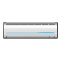
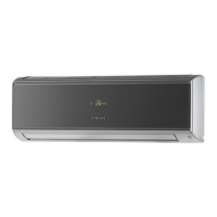
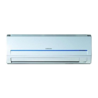
AQ18B1QE
OUTDOOR
UQ24A1QE
UQ24B1QE
UQ18A1QE
UQ18B1QE

Questions and Answers:

Samsung AQ18B1QE Specifications

General IconGeneral
BrandSamsung
ModelAQ18B1QE
CategoryAir Conditioner
LanguageEnglish

Summary

1. Precautions

2. Product Specifications

2-1 Table

Detailed specifications for air conditioner models.

2-2 MAJOR COMPONENT SPECIFICATIONS

Specifications for major indoor and outdoor unit components.

2-3 Dimensions

Dimensional drawings and measurements for indoor and outdoor units.

2-4 Pressure Graph

Graphs showing pressure variations based on outdoor inlet air temperature.

3. Operating Instructions and Installation

3-1 Operating Instructions

Details on remote control buttons and operating modes.

3-2 Installation

Guidelines for selecting installation areas and procedures.

4. Disassembly and Reassembly

4-1 Indoor Unit

Procedure for disassembling the indoor unit's front grille and related parts.

4-2 Outdoor Unit

Procedure for disassembling the outdoor unit's cabinet and fan.

5. Troubleshooting

5-1 Items to be checked first

Initial checks and common issues before diagnosing faults.

5-2 Fault Diagnosis by Symptom

Troubleshooting steps for various operational symptoms.

5-3 PCB Inspection

Safety and procedures for inspecting and replacing PCB parts.

5-4 Fault Diagnosis of Major Parts

Diagnostic methods for major components like sensors and motors.

6. Exploded Views and Parts List

6-1 Indoor Unit

Exploded view diagram and parts list for the indoor unit.

6-2 Outdoor Unit

Exploded view diagrams and parts lists for outdoor units.

6-3 Remote Control & PCB Box

Exploded views and parts lists for remote control and PCB box.

7. Block Diagrams

7-1 Refrigerating Cycle Block Diagram

Block diagram illustrating the refrigerating cycle of the unit.

8. PCB Diagrams

8-1 Main PCB(DB93-10545B) : 24K BTU (DB93-10555B) : 18K BTU

Diagram of the main PCB for 24K and 18K BTU models.

8-2 ASS'Y DISPLAY & Module

Exploded views and parts lists for display assemblies.

9. Wiring Diagrams

9-1 Indoor Unit

Wiring diagram for the indoor unit.

9-2 Outdoor Unit

Wiring diagrams for outdoor units.

10. Schematic Diagrams

10-1 Indoor Unit

Schematic diagram for the indoor unit.

Related product manuals