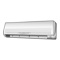
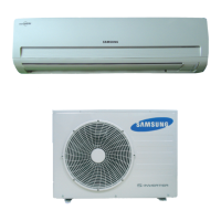
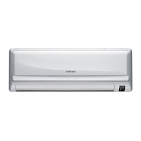
This document serves as a comprehensive service manual for the Samsung ROOM AIR CONDITIONER, specifically for indoor unit model AQ30C2BC and outdoor unit model UQ30C2BC. It provides detailed instructions for installation, disassembly, reassembly, troubleshooting, and includes exploded views, parts lists, refrigerating cycle block diagrams, wiring diagrams, and schematic diagrams.
Function Description:
The Samsung ROOM AIR CONDITIONER is designed to provide cooling and heating functionalities for indoor spaces. It operates by circulating refrigerant through an indoor evaporator unit and an outdoor condenser unit, facilitating heat exchange to regulate room temperature. The system includes various components such as a compressor, fan motors for both indoor and outdoor units, a 4-way valve for switching between cooling and heating modes, and a control system with sensors and a main PCB to manage operation.
Important Technical Specifications:
- Indoor Unit Model: AQ30C2BC
- Outdoor Unit Model: UQ30C2BC
- Refrigerant Refill Procedure:
- Standard pressure for regular, high operation mode: 4.5~5.5 kg/cm².
- Input Voltage: Rating voltage ±10% range.
- DC Regulator IC KA7805 (IC02):
- Input voltage: 11.5VDC-12.5VDC
- Output voltage: 4.5VDC-5.5VDC
- Indoor Unit Fan Motor Supply Voltage: AC 180V (measured at PCB CN73, pin3, pin5 during fan operation).
- Room Sensor Normal Register (at 25°C): 10 kΩ.
- 10°C: 17.96 kΩ
- 20°C: 12.09 kΩ
- 30°C: 8.3 kΩ
- Power Relay RY71 (Compressor) / RY73 (4-way valve) / RY72 (Outdoor fan) Voltage: DC 12V.
- Solid State Relay (SS71) Voltage: 12V.
- Micom (IC04) Pin #43 (Heat mode): DC 4.8V.
- IC06 (KID65003) Pin #16 (Heat mode): LOW (0V).
- Voltage between CN71 #5 and CN78 #1 (Heat mode): Rating voltage ±10% range.
- Remote Control Unit Battery Voltage: Should be greater than 2.5V.
- Refrigerating Cycle STD Pressure (3-Way Valve):
- Cooling: 57-71 psi
- Heating: 270-327 psi
- Refrigerating Cycle Piping Temperature (T1/T2):
- Cooling (Standard): 46-54°F
- Heating (Standard): 90-97°F (T1), 140-158°F (T2)
- Use Temperature Conditions (Indoor DB/WB, Outdoor DB/WB):
- Cooling (Standard): Indoor 80/67°F, Outdoor 95/75°F
- Cooling (Max over load): Indoor 80/67°F, Outdoor 115/75°F
- Cooling (Low temp): Indoor 67/57°F, Outdoor 67/57°F
- Heating (Standard): Indoor 70/59°F, Outdoor 47/43°F
- Heating (Max over load): Indoor 80/--°F, Outdoor 75/65°F
- Heating (Low temp): Indoor 70/59°F, Outdoor 35/33°F
Usage Features:
The air conditioner offers various operational modes, including Cool, Heat, Dry, and Auto. Users can control the unit via a remote control, which allows for setting temperature, fan speed, and activating functions like the timer. The indoor unit features an LED display that blinks to indicate power status, timer activation, or specific self-diagnosis errors.
- Cool Operation Mode: The compressor operates based on the room temperature relative to the set temperature.
- Heat Operation Mode: The compressor and indoor/outdoor fans adjust operation to maintain the set temperature. De-ice activation can cause the compressor to continue running for up to 9 minutes after the unit is turned off.
- Dry Mode: Fan speed is automatically set to LL (low) and compressor operation is controlled based on room temperature and humidity.
- Auto Mode: Fan speed is automatically selected from 5 steps.
- Self-Diagnosis Display: The indoor unit's display panel provides visual cues (LED blinking patterns) for various operational conditions and errors, such as:
- STD LED blinking (1Hz): Restore from power failure (initial power input).
- TIMER LED blinking (1Hz): Indoor unit Room sensor Error (open or short).
- STD and TIMER LED blinking (1Hz): Indoor unit heat exchanger temperature sensor Error (open or short).
- BIO LED blinking (1Hz): Indoor fan malfunctioning (for speed below 450rpm).
- STD, BIO and TIMER LED blinking (1Hz): EEPROM Error.
- All LED blinking (1Hz): Option Error (option wasn't setup or option data error).
- Remote Control Operation: The unit responds to ON/OFF, swing button, and other commands from the remote control. A "beep" sound confirms successful command reception.
Maintenance Features:
The manual details several procedures for maintenance and repair, emphasizing safety precautions such as stopping operation and removing the power cord before any work.
- Refrigerant Refill Procedure:
- Purge air (for new installations).
- Connect a pressure gauge to the service valve.
- Connect the refrigerant tank.
- Set the unit to cool operation mode.
- Monitor pressure gauge (low pressure side) to ensure it's within 4.5~5.5 kg/cm².
- Gradually fill with refrigerant until the rated pressure is reached.
- Stop operation, disconnect the gauge, and close valve caps.
- "Pump Down" Procedure (for evaporator replacement or unit relocation):
- Remove caps from 2-way and 3-way valves.
- Connect a pressure gauge to the service valve and open the 3-way valve.
- Set the unit to cool operation mode (ensure compressor is operating).
- Close the 2-way valve.
- When the pressure gauge indicates "0", close the 3-way valve.
- Stop operation.
- Close valve caps.
- Relocation of the Air Conditioner:
- Perform the pump down procedure.
- Remove the power cord.
- Disconnect assembly cables from indoor and outdoor units.
- Remove flare nuts connecting indoor unit and pipe, covering pipes to prevent foreign material entry.
- Disconnect pipes from outdoor unit, covering valves and pipes.
- Store connection pipes and cables carefully, avoiding bending.
- Move indoor and outdoor units.
- Remove and relocate the indoor unit's mounting plate.
- Disassembly and Reassembly (Indoor Unit):
- Front Grille: Involves separating tape, opening the inlet grille, removing filters (including optional deodorizing and electrostatic filters), loosening fixing screws, separating the terminal cover, and carefully pulling out the upper and lower parts of the discharge.
- Ass'y Tray Drain: Requires separating the drain hose, removing the display PCB, and pulling out the tray drain.
- Electrical Parts (Main PCB): Involves disconnecting all PCB connectors (including earth wire), separating the outdoor unit connection wire from the terminal block, and pulling up the Main PCB.
- Heat Exchanger: Requires loosening fixing screws on both sides, separating holder-back body parts, and lifting the heat exchanger for separation.
- Fan Motor and Cross Fan: Involves loosening fixing screws, separating the holder motor, separating the fan motor from the right fan, loosening the fixing screw of the left fan, and separating both fans from the back body.
- Disassembly and Reassembly (Outdoor Unit):
- Cover Top: Loosen screws and remove.
- Back Cabi: Loosen screws and remove.
- Control Box: Loosen screw, remove, and separate wiring.
- Cover Front: Loosen screws and remove.
- Troubleshooting Procedures: Detailed flowcharts guide technicians through diagnosing issues such as "No Power," "Indoor Unit Fan Does Not Operate," "Outdoor Unit Does Not Operate," "UP/DOWN Louver Motor Does Not Operate," "No Warm Air Current (Heat Mode)," and "Impossible Operation By Remote Control Unit." These procedures involve checking voltages, component functionality (e.g., relays, sensors, micom), and connections.
- PCB Module Replacement: A procedure for replacing the PCB module, including checking connections and setting up model options.
- Parts Lists: Comprehensive lists for both indoor and outdoor units, including part numbers, descriptions, specifications, and quantities, facilitating easy identification and ordering of replacement parts.
- Wiring and Schematic Diagrams: Provide visual representations of the electrical connections and internal circuitry, essential for understanding the system's operation and for accurate troubleshooting.