10
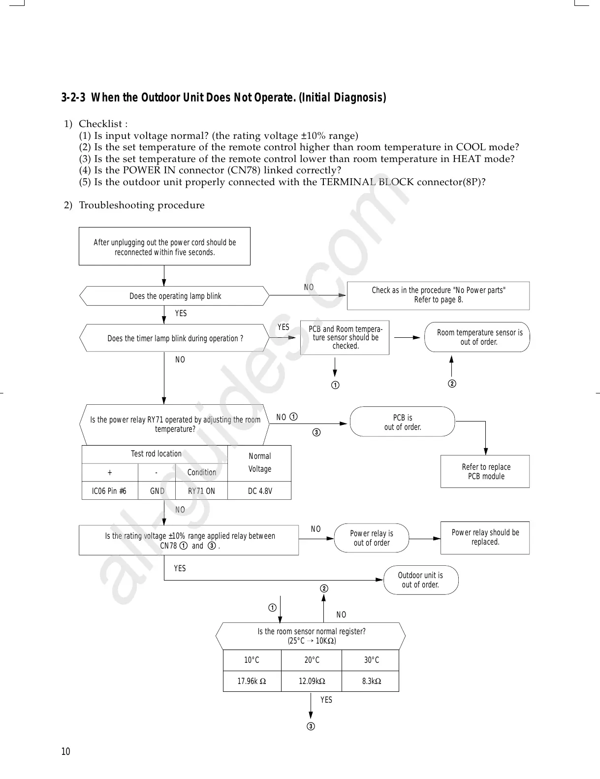
3-2-3 When the Outdoor Unit Does Not Operate. (Initial Diagnosis)
1) Checklist :
(1) Is input voltage normal? (the rating voltage ±10% range)
(2) Is the set temperature of the remote control higher than room temperature in COOL mode?
(3) Is the set temperature of the remote control lower than room temperature in HEAT mode?
(4) Is the POWER IN connector (CN78) linked correctly?
(5) Is the outdoor unit properly connected with the TERMINAL BLOCK connector(8P)?
2) Troubleshooting procedure
After unplugging out the power cord should be
reconnected within five seconds.
Does the operating lamp blink
YES
YES
NO
NO
NO
NO
NO
YES
NO
Outdoor unit is
out of order.
Power relay is
out of order
Power relay should be
replaced.
Refer to replace
PCB module
PCB is
out of order.
PCB and Room tempera-
ture sensor should be
checked.
Room temperature sensor is
out of order.
Check as in the procedure "No Power parts"
Refer to page 8.
YES
@
@
!
!
!
#
#
Is the room sensor normal register?
(25°C
→ 10KΩ)
10°C 20°C 30°C
17.96k Ω 12.09kΩ 8.3kΩ
Does the timer lamp blink during operation ?
Is the power relay RY71 operated by adjusting the room
temperature?
Is the rating voltage ±10% range applied relay between
CN78 ! and # .
Test rod location
+ - Condition
IC06 Pin #6 GND RY71 ON DC 4.8V
Normal
Voltage
DB98-05109A(1)-1 3/11/02 12:46 PM Page 10
 Loading...