EasyManua.ls Logo

Samsung AR09TSFYBWKNCV User Manual

Samsung AR09TSFYBWKNCV
108 pages
To Next Page IconTo Next Page
Page #1 background imageLoading...
Page #1 background image
AIR CONDITIONER CONTENTS
SPLIT-TYPE AIR CONDITIONER
OUTDOOR UNIT
MODEL CODE
INDOOR UNIT
1. Precautions
2.
3. Alignment and Adjustments
4. Disassembly and Reassembly
5. Assy Control
6. Wiring Diagram
7. PCB Diagram
8. Operating Instructions
9. Troubleshooting
10. Block Diagram
11. Reference Sheet
AR09TSFABWKNCV
AR12TSFABWKNCV
AR09TSFYBWKNCV
AR12TSFYBWKNCV
AR18TSFYBWKNCV
AR18TSFABWKNCV
AR24TSFYBWKNCV
AR24TSFABWKNCV
AR09TSFACWKXCV
AR09TSFABWKXCV
AR12TSFACWKXCV
AR12TSFABWKXCV
AR09TSFYBWKXCV
AR12TSFYBWKXCV
AR18TSFYBWKXCV
AR18TSFACWKXCV
AR18TSFABWKXCV
AR24TSFYBWKXCV
AR24TSFACWKXCV
AR24TSFABWKXCV
AR**TSFY*WKNCV
AR09TSF**WKXCV
AR12TSF**WKXCV
AC071RXADKG
AR**TSFA*WKNCV
AR18TSFYBWKXCV
AR18TSFACWKXCV
AR18TSFABWKXCV
AR24TSFYBWKXCV
AR24TSFACWKXCV
AR24TSFABWKXCV

Table of Contents

Other manuals for Samsung AR09TSFYBWKNCV

Question and Answer IconNeed help?

Do you have a question about the Samsung AR09TSFYBWKNCV and is the answer not in the manual?

Samsung AR09TSFYBWKNCV Specifications

General IconGeneral
Energy Efficiency Ratio (EER)3.52
EER3.52
Power Supply220-240V, 50Hz
RefrigerantR32
Weight (Indoor Unit)8.5 kg
TypeSplit
Capacity9000 BTU
Cooling Capacity9000 BTU/h
Operating ModeFan
FeaturesDigital Display
Operating Temperature (Cooling)16°C to 32°C
Operating Temperature (Heating)-5°C to 24°C

Summary

Alignment and Adjustments

Disassembly and Reassembly

4-1 Indoor Unit

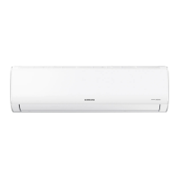
Detailed procedure for disassembling and reassembling the indoor unit components.

4-2 Outdoor Unit (N-SI)

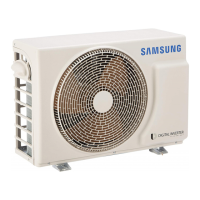
Instructions for disassembling and reassembling the outdoor unit (N-SI model).

4-3 Outdoor Unit (Q)

Instructions for disassembling and reassembling the outdoor unit (Q model).

4-4 Outdoor Unit (P)

Instructions for disassembling and reassembling the outdoor unit (P model).

4-5 Outdoor Unit (UB)

Instructions for disassembling and reassembling the outdoor unit (UB model).

Wiring Diagram

PCB Diagram

7-1 Indoor Main PCB

Schematic and pinout details for the indoor unit's main printed circuit board.

7-2 Outdoor PCB Inverter

Diagram and connector information for the outdoor unit's inverter PCB.

Troubleshooting

9-2 Communication Error

Troubleshooting steps for communication errors between indoor and outdoor units.

9-2-2 Indoor temperature sensor Error

Procedure to diagnose and resolve indoor temperature sensor errors.

9-2-3 Indoor fan motor speed detecting error (BLDC fan)

Troubleshooting guide for indoor fan motor speed detection errors.

9-2-4 Outdoor temperature sensor error

Steps to identify and fix outdoor temperature sensor errors.

9-2-5 Outdoor Cond temperature sensor error

Diagnostic steps for outdoor condenser temperature sensor errors.

9-2-6 Outdoor Discharge temperature sensor error

Troubleshooting for outdoor discharge temperature sensor errors.

9-2-7 Operation condition secession error

Procedure to resolve operation condition secession errors.

9-2-8 EEPROM error / OTP error

Steps to address EEPROM or OTP errors in the air conditioner.

9-2-9 Outdoor Fan motor error

Guide to troubleshooting outdoor fan motor errors.

Block Diagram

Related product manuals