Do you have a question about the Samsung AR09TXFYAWKNEU and is the answer not in the manual?
Guidance on safe and proper installation practices.
Instructions for safe electrical connection and circuit protection.
Guidelines for safe and optimal use of the air conditioner.
Procedures for safe and environmentally friendly unit disposal.
Additional safety and handling precautions.
Overview of key features and functionalities of the air conditioner.
Detailed technical specifications for different models.
Comparison of specifications across different product models.
Details on available accessories and optional features.
Procedures for operating and testing the unit's functions.
Explains error codes and diagnostic methods for troubleshooting.
Guide to configuring various operational settings via the remote.
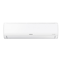
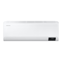
Step-by-step guide for disassembling the indoor unit.
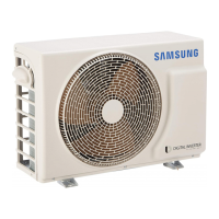
Step-by-step guide for disassembling the outdoor unit.
Lists assembly kit codes for specific models.
Lists assembly kit codes for specific models.
Detailed list of electrical components for the indoor main PCB.
Detailed list of electrical components for the display PCB.
Electrical wiring schematic for the indoor unit.
Electrical wiring schematic for the outdoor unit.
Diagram showing connections on the indoor main PCB.
Diagram showing connections on the outdoor main PCB.
Diagram showing connections on the display PCB.
Illustrates correct wire connections for indoor terminal blocks.
Identifies and explains the main parts of the indoor unit.
Details the buttons and display functions of the wireless remote.
Basic troubleshooting steps before diagnosing specific errors.
Diagnosing and resolving indoor/outdoor communication issues.
Troubleshooting indoor temperature sensor faults.
Diagnosing and resolving indoor fan motor speed errors.
Troubleshooting outdoor temperature sensor faults.
Troubleshooting outdoor condensation sensor faults.
Troubleshooting outdoor discharge sensor faults.
Resolving errors related to prohibited operation conditions.
Diagnosing and resolving EEPROM or OTP related errors.
Troubleshooting outdoor fan motor faults.
Diagnosing and resolving compressor starting issues.
Troubleshooting compressor wire missing or rotation errors.
Diagnosing current sensor and input current sensor errors.
Troubleshooting Over Current (O.C) errors.
Diagnosing and resolving outdoor unit no-power issues.
Troubleshooting issues with louver motor operation.
Resolving problems when the remote control is not recognized.
Troubleshooting errors encountered during the Smart Install process.
Diagnosing outdoor OLP over temperature errors.
Schematic showing the internal components and connections of the indoor unit.
Schematic showing the internal components and connections of the outdoor unit.
Important precautions before performing inspection and maintenance.
General steps for inspecting PCBs and components.
Specific inspection steps for the indoor unit.
Specific inspection steps for the outdoor unit.
Chart showing refrigerant pressure based on temperature.
Table relating capacity units to pressure.
Frequently asked questions and answers for common issues.
Instructions for cleaning the unit and changing filters.
Comprehensive guide for installing the air conditioner.
Visual diagrams for installation procedures.
| Wi-Fi | Yes |
|---|---|
| Type | Air conditioner indoor unit |
| Multi-split | - |
| Display type | LED |
| Product color | White |
| Refrigerating medium | R32 |
| Dehumidifying capacity | 1 l/h |
| Timer duration (maximum) | 24 h |
| Air conditioner functions | Cooling, Dehumidifying, Heating |
| Cooling capacity in watts (nominal) | - W |
| AC input voltage | 220 - 240 V |
| AC input frequency | 50 Hz |
| Hourly energy consumption (heating) | - kWh |
| Design load (heating) (Warmer heating season) | - kW |
| Indoor unit type | Wall-mountable |
| Indoor unit depth | 215 mm |
| Indoor unit width | 820 mm |
| Indoor unit height | 299 mm |
| Indoor unit weight | 9100 g |
| Indoor units quantity | 1 |
| Indoor unit package depth | 375 mm |
| Indoor unit package width | 880 mm |
| Indoor unit package height | 290 mm |
| Indoor unit package weight | 11100 g |
| Cooling airflow (indoor unit) | 630 m³/h |
| Indoor unit sound power level | 54 dB |
| Indoor unit noise level (low speed) | 19 dB |
| Indoor unit noise level (high speed) | 37 dB |
| Outdoor unit noise level | - dB |