Do you have a question about the Samsung DH24ZAX and is the answer not in the manual?
Detailed technical specifications for duct type air conditioners, including capacity, power, and performance metrics.
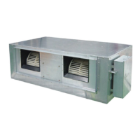
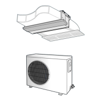
Physical dimensions for indoor and outdoor units, crucial for installation site assessment.
Explains the buttons and display functions of wired and wireless remote controllers for operation.
Details the display unit on the wall and the functions of its indicators and buttons.
Describes the named keys and their functions for both wired and wireless remote controllers.
Illustrates the overall control system and how different units and modes interact.
Explains how to operate remote controllers, including wired and wireless types, for system setup.
Covers the appearance, characteristics, and configuration of the centralized controller.
Guidelines for choosing suitable indoor and outdoor unit locations, considering ventilation and accessibility.
Covers outdoor and indoor unit mounting, piping, drain hose, and insulation installation steps.
Details grounding, cable connections, refrigerant refill, and leak testing procedures.
Information on adjusting fan speed, cleaning the unit, and understanding operating ranges.
Guides for installing wired, wireless, and centralized controllers, including group control setup.
Procedures for checking and testing the installed air conditioner to ensure correct operation.
Step-by-step guide for disassembling key components of the indoor unit for maintenance or repair.
Procedures for disassembling the outdoor unit's cabinet and fan motor for service.
Lists error codes related to the outdoor unit and their potential causes for quick reference.
Explains error indications on the indoor unit's receive and display unit based on LED patterns.
Provides a summary of error codes displayed on the wired remote controller and their corresponding meanings.
Provides flowcharts and diagnostic steps for specific error codes (EC01-EC19) to identify faults.
Detailed list of parts for the indoor unit, including part numbers and specifications.
Comprehensive list of parts for the outdoor unit, specifying part numbers and their respective models.
Illustrates the refrigerant flow and cycle for different models of the air conditioner.
Provides a table correlating temperature readings with thermistor resistance values for accurate diagnosis.
Schematic diagrams and component lists for the main PCB of indoor units (18K/24K and 32K models).
Schematic diagrams and component lists for the main PCB of outdoor units (18K/24K and 32K models).
Detailed schematic diagram illustrating the internal electrical connections of the indoor unit.
Detailed schematic diagram showing the electrical connections within the outdoor unit.
Wiring diagram for the wired remote controller, showing connections to the main unit.
Wiring diagram for the centralized controller, illustrating its connections to multiple units.
Wiring diagram specific to the indoor unit, detailing connections for various components.
Wiring diagram for the outdoor unit, showing interconnections and power supply.
| Brand | Samsung |
|---|---|
| Model | DH24ZAX |
| Category | Air Conditioner |
| Language | English |