EasyManua.ls Logo

Samsung DH175GZM User Manual

Samsung DH175GZM
86 pages
To Next Page IconTo Next Page
Page #1 background imageLoading...
Page #1 background image
5)&'&"563&0'130%6$5"*3$0/%*5*0/&3
5;56'/#+4%10&+6+10'4
&*)</
(QTOQTGKPHQTOCVKQP2NGCUGCEEGUUVQQWTUGTXKEGYGDUKVGJVVRKVUGNHUGEUCOUWPIEQMT
7*)</%
7*)</%7*)</
%
/QFGN
&*)</7*)</%
&*)</7*)</
%
&*)</7*)</
%
$CUKE
**'</ 7*)</
&*)</

'CUKGT+PUVCNNCVKQP
5NKO5K\G

'CUKGT6WPKPI
7UKPI2JCUG%QPVTQN/QVQT

8CTKQWUWUGHWN(WPEVKQPU

%QPXGPKGPV%QPVTQN(WPEVKQPU
Question and Answer IconNeed help?

Do you have a question about the Samsung DH175GZM and is the answer not in the manual?

Samsung DH175GZM Specifications

General IconGeneral
Voltage220-240V
RefrigerantR410A
Weight (Outdoor Unit)35 kg
Power SupplySingle Phase
Operating Temperature (Cooling)18°C to 43°C

Summary

THE FEATURE OF PRODUCT

Easier Installation

Slim height and light weight.

Easier Tuning

Using Phase Control Motor.

Convenient Control Functions

Auto Change Over, Central Controller, Group Control, Weekly program.

1. Precautions

1-1 Installing the air conditioner

Guidelines for installing the air conditioner.

1-2 Power supply and circuit breaker

Requirements for power supply and circuit breaker.

1-3 During operation

Precautions during operation.

2. Product Specifications

2-3 Product Specifications

Detailed technical specifications of the product.

2-2 Name of Each Part

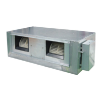
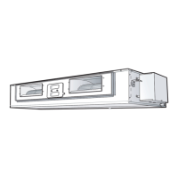
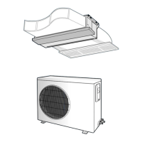
Identification of parts for indoor and outdoor units.

3. Alignment and Adjustments

4. Disassembly and Reassembly

4-1 Indoor Unit

Steps for disassembling and reassembling the indoor unit.

5. Exploded Views and Parts List

5-1 Indoor Unit

Exploded view and parts list for the indoor unit.

6. Electrical Parts List

7. Wiring Diagram

7-1 Indoor Unit

Wiring diagram for the indoor unit.

8. Schematic Diagram

8-1 Indoor Unit

Schematic diagram for the indoor unit.

9. Circuit Descriptions

9-2 Refrigerating Cycle Diagram

Diagram of the refrigerating cycle.

10. PCB Diagram

10-1 Indoor Unit

PCB diagram for the indoor unit.

11. Operating Instruction and Installation

11-1 Main Function

Basic operating functions of the air conditioner.

11-3 Wired Remote Controller-Buttons and Display

Explanation of remote controller buttons and display.

12. Troubleshooting

12-3 Sequence for trouble diagnosis

Step-by-step diagnosis procedures.

13. Block Diagram

13-1 Indoor Unit

Block diagram of the indoor unit.

14. Reference Sheet

14-4 Q & A for Non-trouble

Frequently asked questions and answers.

14-5 Cleaning your Air Conditioner

Instructions for cleaning the air conditioner.

14-6 Installation

Procedures and guidelines for installation.

14-7 Installation Diagram of Indoor Unit and Outdoor Unit

Diagrams for installation, including air purge.

4. Disassembly and Reassembly

4-1 Indoor Unit (DH105GZM)

Steps for disassembling the DH105GZM indoor unit.

Disassembly and Reassembly

4-2 Outdoor Unit (UH140GZM1C/175GZM)

Steps for disassembling the outdoor unit.

5. Exploded Views and Parts List

5-1 Indoor Unit (DH105GZM)

Exploded view and parts list for DH105GZM indoor unit.

5-2 Outdoor Unit

UH105GZM1C

Exploded view and parts list for UH105GZM1C outdoor unit.

UH140GZM1C/UH175GZMC

UH140GZM1C/UH175GZMC

Exploded view and parts list for UH140GZM1C/UH175GZMC outdoor units.

6. Electrical Parts List

Indoor PCB : DB93-03213*

Electrical parts list for Indoor PCB.

Outdoor PCB : DB93-02919H(UH105GZM1C)

Outdoor PCB : DB93-02919H(UH105GZM1C)

Electrical parts list for Outdoor PCB.

Outdoor PCB : DB93-02919G(UH140GZM1C)

Outdoor PCB : DB93-02919G(UH140GZM1C)

Electrical parts list for Outdoor PCB.

Outdoor PCB : DB93-02919E(UH175GZMC)

Outdoor PCB : DB93-02919E(UH175GZMC)

Electrical parts list for Outdoor PCB.

Wiring Diagram

UH140GZM1C

Wiring diagram for UH140GZM1C outdoor unit.

UH175GZMC

UH175GZMC

Wiring diagram for UH175GZMC outdoor unit.

10. PCB Diagram

10-2 Outdoor Unit PCB Legend

Legend for outdoor unit PCB components.

11. Operating Instruction and Installation

Selecting the Automatic Operating Mode

Steps to select and adjust automatic operating mode.

Cooling Your Room

Instructions for cooling the room.

Main Function (cont.)

Heating Your Room

Instructions for heating the room.

Operating Instruction and Installation

Removing Excess Humidity

Instructions for removing excess humidity.

Airing Your Room

Instructions for airing the room.

11-2 Additional Function

Compensation for lost temperature in heating operation

Adjusting for temperature loss in heating.

Adjusting filter cleaning cycle

Adjusting the filter cleaning indicator cycle.

Hot water heater

Instructions for installing hot water heater.

External Control

Instructions for using external control.

External Control (cont.)

<Operation ON/OFF Function>

Functionality for ON/OFF control.

<Operation State Display>

Display of operation status.

12. Troubleshooting

12-1 Operation Specification

Details of operation specifications and display tracking.

Troubleshooting

12-1-3 Setting Up Option Switches

Procedures for setting up option switches.

12-2 Troubleshooting

12-2-1 Wired remote controller display error occurring

Troubleshooting wired remote controller display errors.

Troubleshooting

12-2-2 LED Display on the receiver & display unit

Understanding LED display error codes.

Troubleshooting

12-2-3 Outdoor Unit

Troubleshooting errors displayed on outdoor unit PCB.

Troubleshooting

12-3 Sequence for trouble diagnosis

Step-by-step diagnosis procedures.

Troubleshooting

12-3-2 Outdoor heat exchanger temp. sensor error(OPEN/SHORT)

Diagnosing heat exchanger sensor errors.

Troubleshooting

12-3-3 Outdoor discharge temp. sensor error(OPEN/SHORT)

Diagnosing discharge temperature sensor errors.

Troubleshooting

12-3-4 Communication error during the operation

Troubleshooting communication errors.

Troubleshooting

Troubleshooting

12-3-6 Indoor float switching error

Diagnosing indoor float switch errors.

13. Block Diagram

13-1 Indoor Unit

Block diagram of the indoor unit.

14. Reference Sheet

14-1 Index for Model Name

Index for identifying model names.

14-6 Installation

14-6-1 Before Installation

Guidelines and requirements before installation.

14-6-2 Installation Procedure

Step-by-step procedure for installation.

14-7 Installation Diagram of Indoor Unit and Outdoor Unit

14-7-1 Air-Purge Procedure

Procedure for purging air from the system.

Reference Sheet

14-7-2 "Pump down" Procedure

Procedure for pump down operation.

Related product manuals