Do you have a question about the Samsung DH32ZAX and is the answer not in the manual?
Detailed technical specifications for duct type air conditioners, covering various models and parameters.
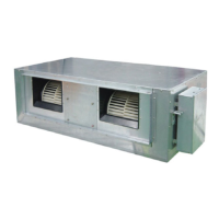
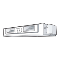
Provides dimensional drawings and measurements for indoor and outdoor units.
Explains the buttons and display elements of the wired remote controller for operation.
Details the buttons and display functions of the wireless remote controller for unit operation.
Describes the features and operation of the optional centralized controller for managing multiple units.
Illustrates the receiver and display unit mounted on the wall and its indicators.
Details the functions of each button on the wired remote controller for unit operation.
Explains the functions of each button on the wireless remote controller for unit operation.
Illustrates the system diagram for controlling air conditioners via various controllers.
Shows the block diagram of the microcomputer system for the indoor unit's operation.
Describes how to operate the air conditioner using wired and wireless remote controllers.
Provides guidelines for selecting suitable locations for installing the indoor and outdoor units.
Provides detailed steps and precautions for the proper installation of the indoor unit.
Details the procedure for ensuring proper grounding of the air conditioning unit for safety.
Details the process of connecting the refrigerant pipes to the indoor unit assembly.
Details the disassembly and reassembly procedures for the indoor unit components.
Outlines the disassembly and reassembly procedures for the outdoor unit components.
Lists error codes related to the outdoor unit and their corresponding troubleshooting steps.
Details error codes displayed on the indoor unit receiver board and troubleshooting steps.
Provides an exploded view and a detailed parts list for the indoor unit.
Displays an exploded view and parts list for the 18K outdoor unit.
Displays an exploded view and parts list for the 24K outdoor unit.
Displays an exploded view and parts list for the 32K outdoor unit.
Illustrates the refrigerating cycle block diagram for the ADH1800E, DH18ZA1(A2) model.
Shows the refrigerating cycle block diagram for the ADH2400E, DH24ZA1(A2) model.
Presents the refrigerating cycle block diagram for the ADH3200E, DH32ZA1(A2) model.
Provides a table of thermistor resistance values at different temperatures for model 103AT.
Displays the main PCB layout for the air conditioning unit.
Shows the PCB diagram for the indoor unit of 18K and 24K models.
Presents the PCB diagram for the indoor unit of the 32K model.
Shows the PCB diagram for the outdoor unit of 18K and 24K models.
Presents the PCB diagram for the outdoor unit of the 32K model.
Provides the wiring diagram for the indoor unit of the air conditioner.
Shows the wiring diagram for the outdoor unit of the air conditioner.
Presents the schematic diagram for the wired remote controller.
Shows the schematic diagram for the centralized controller system.
Displays the schematic diagram for the indoor unit of specific models.
Presents the schematic diagram for the outdoor unit of specific models.
| Model | DH32ZAX |
|---|---|
| Power Supply (Φ/V/Hz) | 1/220/50 |
| Net Weight (kg) | 9.0 kg |
| Refrigerant Control | Electronic Expansion Valve |
| Piping Connections Liquid (mm) | 6.35 mm |
| Operating Temp. Range Heating (°C) | -15 ~ 24 °C |
| Power Supply | 1 / 220-240 / 50 |