Do you have a question about the Samsung DVD-P241 and is the answer not in the manual?
Covers essential safety checks before returning equipment and during servicing, including protective devices and openings.
Details general and specific safety guidelines for servicing the unit, including unplugging power and handling components.
Outlines procedures to prevent damage from electrostatic discharge to sensitive components like ICs and transistors.
Provides recommended methods for safely handling the optical pick-up unit to prevent electrostatic breakdown.
Explains the correct sequence for disassembling and reassembling the optical pick-up assembly to avoid damage.
Identifies specific test points on the main PCB for alignment and adjustment procedures, referencing component RIC1.
Details the procedure for skew adjustment to optimize signal matching on the disc, involving specific screws.
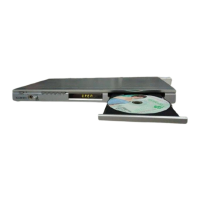
Provides an exploded view and parts list for the unit's cabinet components, including the chassis and remote.
Details the exploded view and parts list for the internal deck mechanism, covering motors, gears, and chassis.
Detailed schematic for the power supply circuit of the DVD player, showing primary and secondary sections.
Schematic diagram for the AV decoder and main microcontroller unit, illustrating connections and ICs.
Circuit diagram illustrating the servo control system for disc playback, including motor drivers and feedback.
Schematic showing the video processing and output circuitry, including the video encoder and output jacks.
Circuit diagram detailing the audio processing and output stages, featuring the audio DAC and amplifier ICs.
Schematic representing the button input and remote control signal handling, including key matrix and IR receiver.
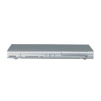
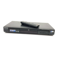
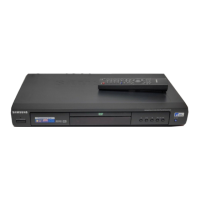
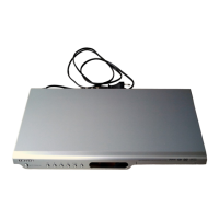
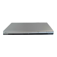
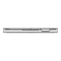
| Brand | Samsung |
|---|---|
| Model | DVD-P241 |
| Category | DVD Player |
| Language | English |