Do you have a question about the Samsung MAX- WL85 and is the answer not in the manual?
| Category | CD Player |
|---|---|
| Frequency Response | 20Hz - 20kHz |
| Supported Disc Formats | CD |
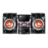
| Model | Samsung MAX-WL85 |
| Output Power | 20W (10W x 2) |
Adjustments and specifications for the tuner section.
Procedures for adjusting tape speed, bias, and playback levels.
Detailed list of electrical components for MAXL82/ZL82.
Block diagram of the main system components and connections.
Overall wiring schematic for common system connections.
Schematic diagram for the power amplifier section.