ENGLISH
13
Refrigerant piping works
Draining form
X
In a standard condition, drain installation is not required
X
In a high humidity condition, drain installation is required
High humidity condition: Indoor temperature of 30°C, relative humidity of 85% within MCU installation space
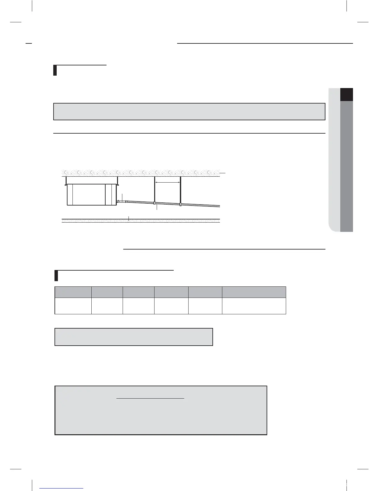
Without the drain pump
1. Install horizontal drain pipe with a slope of 1/100 or more and x it by hanger space of 1.0~1.5m (3.28~4.92')
2. Install U-trap at the end of the drain pipe to prevent a nasty smell to reach the indoor unit.
3. Install U-trap at the end of the drain pipe to prevent a nasty smell to reach the indoor unit.
1.0~1.5m
(3.28~4.92')
Horizontal drainpipe more than 1/100 slope
Ceiling
Hanger
Flexible hose
Installing the circuit breaker and wires
Power supply MCCB ELB Power cable Earth cable Communication cable
Max : 242V
Min : 198V
X A
X A, 30mmA
0.1 sec
0.0039inch
2
(2.5mm
2
)
0.0039inch
2
(2.5mm
2
)
0.0012~0.0023inch
2
(0.75~1.5mm
2
)
The capacity of ELB, MCCB X[A] = 1.25 X 1.1 X ∑Ai
X
Decide the capacity of ELB and MCCB by below formula.
X
Decide the power cable specication and maximum length within 10% power drop among indoor units.
f
DVM Hydro unit HT should use a separated power cable . Do not divide power cable from MCU to Hydro unit HT, MCU may be damaged.
❈
X
: The capacity of ELB, MCCB
❈
∑Ai : Sum of Rating currents of each indoor unit.
❈
Refer to each installation manual about the rating current of indoor unit.
7 Coef: 1.55
7
LK: Distance among each indoor unit[m], Ak: Power cable specification[mm
2
]
i
K: Running current of each unit[A]
∑ (
Coef×35.6×LK×iK
)<
10% of input voltage[V]
1000×A
K
n
k=1
Wiring works
tj|Tz]ullXuptluGWZ[`WhTW]UGGGXZ YWX\TW`TX^GGG㝘㤸GXWa\Za[^
 Loading...