Samsung Electronics 5-1
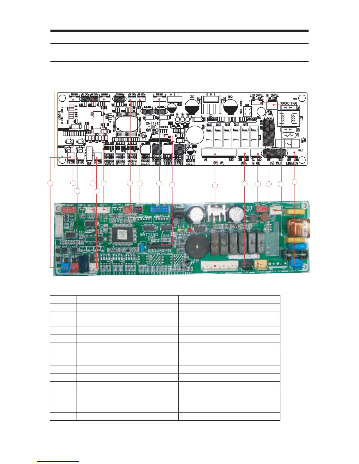
■ 5-1-1 INDOOR MAIN PCB
5. PCB Diagram and Parts List
5-1. Indoor PCB Diagram
1 External control out(Error,comp.status) SMW250-04(RED)
2 Eva-out temp.sensor SMW250-02(WHT)
3 Room/Eva-in temp.Sensor SMW250-04(WHT)
4 External control in(On/Off control) SMW250-02(RED)
5 Floating switch SMW250-02(BLK)
6 Panel Louver(stepping motor) SMW250-06(BLU)
7 Micom Program download SMW200-10(BLK)
8 Trans out SMW250-03(RED)
9 Trans In YW396-03V(WHT)
10 AC power YW396-03V(BLU)
11 Drain Pump YW396-03V(YEL)
12 Ventilator YW396-03V(BLK)
13 Fan Tap YW396-09V(BLK)
14 DC12V out(Wired rmote controller power) YW396-02V(WHT)
15 Communication 1(outdoor_ F1/F2) YW396-02V(RED)
16 Communication 2(Wired Remocon_F3/F4) YW396-02V(BLU)
AC052FBCDEH/ AC071FBCDEH