45
Circuit Descriptions
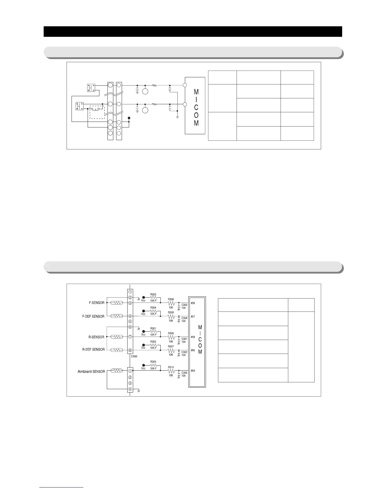
10-4) Door S/W Sensing Circuit
10-5) Temperature Sensing Circuit
1 ) F-Room door open is picked up based on the state (5V/0V) of the MICOM No.43 Port.
When the F-Room door opens, it becomes short between the Door S/W 1 &2.And,5V is supplied in the following
order. CN30 No.⑨→F-Door S/W → CN30 No.①→R408(1 0K)→MICOM 43 PORT
When the state of MICOM 43 PORT is 0V, the door is picked up as closed. When it is 5V, the door is considered to be
open.
2) R-Room door open is picked up based on the state (5V/0V) of the MICOM No.44 Port.
When the R-Room door opens, it becomes short between the Door S/W 1 &2.And,5Vis supplied in the following order.
CN30 No.⑩→R-Door S/W → CN30 No.⑤→R407(1 0K)→MICOM 44 PORT
When the state of MICOM 44 PORT is 0V, the door is picked up as closed. When it is 5V, the door is considered to be
open.
3) When door open is detected, the MICOM have the relevant Fan Motor stop and the relevant Room Lamp light up.
Depending on the state of Door Open/Close, there are following operations; Lamp On/Off, Fan Motor On/Off and Door
open alarm. So, check relevant items upon A/S.
Terminal Operation Volt(state)
Freezer
(MICOM43PORT)
DOOR OPEN
DOOR CLOSE
0V (LOW)
5V (HIGH)
Ref.
(MICOM44PORT)
DOOR OPEN
DOOR CLOSE
0V (LOW)
5V (HIGH)
# of t
erminal in MICOM Remark
PIN #56 (F-SENSOR)
PIN #57 (F-DEF-SENSOR)
PIN #59 (R-SENSOR)
PIN #60 (R-DEF-SENSOR)
PIN #63 (EXT-SENSOR)
Micom
terminal
voltage may
change
according to
temp.
1) A thermistor with a negative temperature coefficient (NTC) is used for a temperature sensor.
2) Resistors, R 306 ∼ R310 and capacitors, C 301 ∼ C 305 are used for a noise protection purpose.
3) For the F-sensor, the input voltage into the micro processor (MICOM), VF is calculated by (Rth x Vcc)/(R303+ Rth),
where Rth is a corresponding resistance to the thermistor’s output (See Ref. 6 in Appendix).
4) The F-Def sensor is connected with a bimetal and a temperature sensor is in parallel. In a normal operation of the
system, the bimetal is on and 0V is input into the micro-processor. During a defrost cycle, the bimetal will be off from
54℉, and a divided voltage with R304 enter to the micro-processor to keep sensing the set temperature.