Check with power applied.
The Door S/W is a two-contact switch. One
detects Door Open/Close with DC 5V at the
PCB and the other one turns on/off the room
light.
(R-Room Light)
1 . Check if the light comes on by opening the R-Door. If it lights up, check if the light goes off by pressing down
the Door S/W with the door open.
If there is any problem, check the R-Door S/W.
(R-Door Open Sensing Part of MAIN PCB)
1 . Place the positive(+) terminal on CN30 No.⑤ and the negative(-) on No.⑩.And,check the voltage.
2. When the voltage is DC 5V with the door open, it is normal.
3. When the voltage is DC 0V with the door closed, it is normal. If there is any problem, check the Door S/W and
the wire connections.
(F-Room Light)
1 . Check if the light comes on by opening the F-Door. If it lights up, check if the light goes off by pressing down
the Door S/W with the door open.
If there is any problem, check the F-Door S/W.
(F-Door Open Sensing Part of MAIN PCB)
1 . Place the positive(+) terminal on CN30 No.① and the negative(-) on No.⑨. And,checkthe voltage.
2. When the voltage is DC 5V with the door open, it is normal.
3. When the voltage is DC 0V with the door closed, it is normal. If there is any problem, check the Door S/W and
the wire connections.
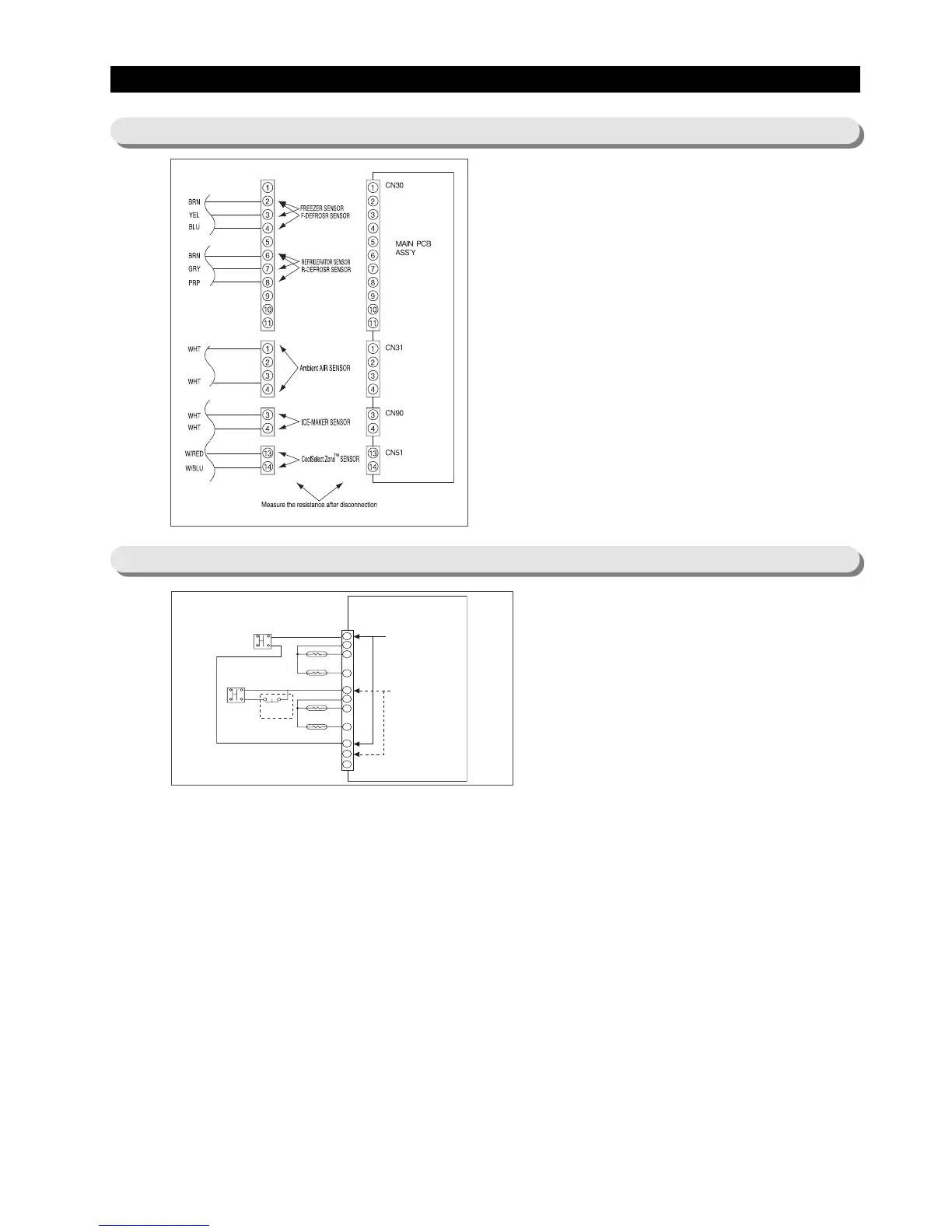
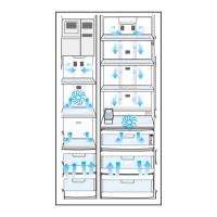
Disconnect the connector from the Main PCB,
than measure the resistance of the following
sensors.
1. Check the resistance the Freezer sensor cn30 between the no. 2 and 3.
2. Check the resistance the Fridge Room sensor cn30 between the no. 6 and 7.
3. Check the resistance the F Defrosting sensor cn30 between the no. 2 and 4.
4. Check the resistance the R Defrosting sensor cn30 between the no. 6 and 8.
5. Check the resistance between the no. ① and ④ the ambient Air sensor cn31.
6. Check the resistance between the no. ③ and ④of the Ice-Maker sensor cn90.
7. Check the resistance between the no. ⑬ and ⑭ of the CoolSelect Zone
TM
sensor cn51.
8. Decide the sensor by comparing above resistances to the temperature of
each sensor with the conversion table of sensor resistance and voltage from
the reference temperature of Ref. 6 on this manual.
※When the resistance is ∞Ωor 0Ω,check the connection of electric wire and
sensorconnector.
Appendix
ⅠⅠ
(Reference for circuit diagnostics)
Ref. 1) Check sensors
Ref. 2) Check Door S/W