Samsung Electronics 4-41
Alignment and Adjustment
Note 2 : How to connect video out signal.
-Connect the video cable to ass’y A/V Jack.
Note 3 : How to record -1. Insert a recordable tape.
-2. Press the SW474 (START/STOP) button on the Rear board in the adjustment
mode.
4-3-2 VCR Section
Note 1 : From this point forward, the structure of every adjustment is as follows.
Test point
Step Adjustment Item
1. Mode and input signal/
alignment tape
2. Test point and ADJ. part
3. Result and Remarks
ADJ. point
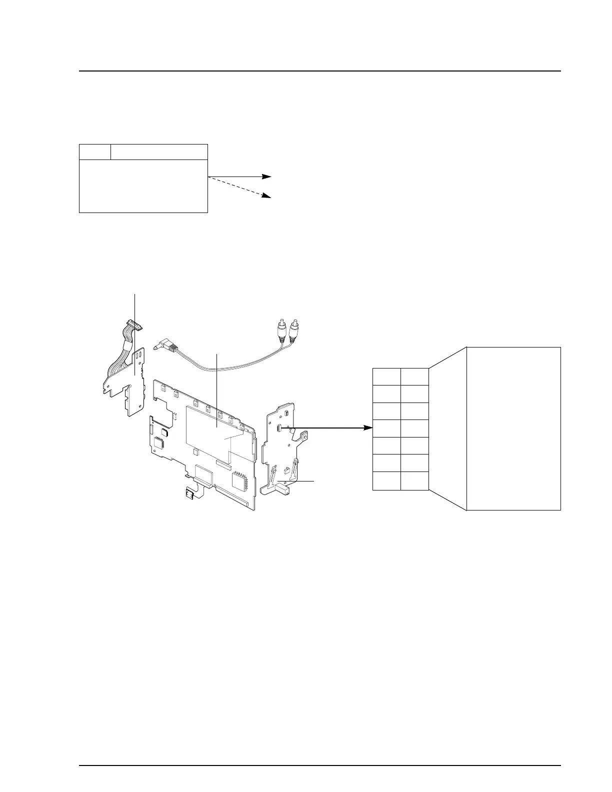
Fig. 1 Video Signal Connection
MAIN PCB
REAR PCB
FRONT PCB
13
VIDEO OUT
12
11
10
9
8
7
6
5
4
3
2
1
NC
PB RF
AUDIO OUT
HD SW
VCR UNREG
JIG CS
VCR UNREG
JIG SCK
SS GND
JIG SO
JIG DETECT
JIG SI
AUDIO GND
14
CN452
14 13
12 11
10 9
87
65
43
21