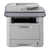
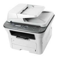
2. Product specifications and descriptions
2-27
Samsung Electronics
Service Manual
SCX-483x/5x3x series
2.2.5.1 Main controller
SCX-483xFD/HD Main Controller is composed with below components
-. CHORUS3 : To generate the printable video data and control engine
Embedded USB2.0 device
-. On board DDR2 SDRAM : system memory(128MB)
External DRR2 SO-DIMM : 256MB
-. Ethernet PHY : 10/100 Network printing
-. NOR Flash : 16MB for Program memory
-. Serial Flash: 8MB For Fax Data
The Main Controller manages an Electro-photography system, controls the Video Data of printing images
from Main Board to LSU, provides high-voltages and PWMs, adjusts temperature in the fusing system, reads
sensor signals and controls SCF option.
The Main controller also controls OPE and N/W PHY [Network], USB Device.
[ Main Controller Diagram ]
Power S/W
CPU: Chorus 3
Clock : 360Mhz
OPE 2line
Buzzer , Power S/W
HVPS Board
(MHV,THV,DEV_DC
,FUSER_BIAS)
LSU
2BEAM
SCF
(Rst,Rx,Tx,REQ)
540?
UART x 4
USB 2.0
MAC
I2C x 2
DDR2 128 M
ONBOARD +
256MB
1 DI MM
NCRUM
PHY IC
AC201A1KMLG
10/100
LAN
USB Device
ADF Unit
Modem
Conexant
ISP1582
EEPROM(64K)
LSU
controller
DDR2
controller
SCAN
IF / AFE
GPIO
PWM x 12
DAC ADCRTC
RTC
battery
Flash(16M)
for OS
Engine (TBD)
- Solenoid ?
(MP,Pickup ,Regi)
- Sensor ?
(Exit, Feed, Empty,
Regi,Out bin full , MP,
ADF_DET, ADF_POS,
ADF_COVER, Duplex)
- Fan (Main,
SMPS,MIDDLE)
Motor
Cover S/W
Debug
MAINBOARD
Fuser
thermistor
1 BLDC
STEP
A3983
Serial Flash (8M)
for FAX
Flash
DCDC
ST1S 10
THV readLD power
SPI
CIS Scan Unit
USB HOST
DCDC
ST1S 10
DCDC
ST1 S10
3. 3V
syste m
1. 8V
DDR
1.0 V
CHO RUS 3
SMPS(TYPE2)
24V, 5V, FDB, Relay
Speaker
LAFE1001
Rainier 31
Block Diagram
2010 .007 .12
Ambient
5V
SMPS
UR5596
0.9V
VTT
H/ W
PROTECT
Home
Sensor
STEP
A3983
 Loading...
