EasyManua.ls Logo

Samsung SV-100G User Manual

Samsung SV-100G
61 pages
To Next Page IconTo Next Page
Page #1 background imageLoading...
Page #1 background image
VIDEO CASSETTE RECORDER
SV-425G/224G/223G
SV-425B/225B/220B
SV-425
I/223I
SV-425X/220X
SV-C30G/SV-6C/5C
SV-A80G(HCII)/A70G(HCII)/A11G(HCII)
SV-122G/121G/120G/100G/C12K
SVR-425/423/420/223/220/121/120
SERVICE
1. Precautions
2. Alignment and Adjustment
3. Exploded View and Parts List
4. Electrical Parts List
5. Schematic Diagrams
Manual
VIDEO CASSETTE RECORDER CONTENTS
For mechanical disassembly and adjustment, refer to the “Mechanical Manual” (DX-9R AC68-00001A).
SERVICE MANUAL
SV-425G/425B/425I/425X/C30G/SVR-425/121/SV-A80G(HCII)
ELECTRONICS
© Samsung Electronics Co., Ltd. DEC. 1998
Printed in Korea
AC68-00112A
POWER
PROG
REC
STOP
PLAY
REW
F.F
LINE IN 2
VIDEO AUDIO
EJECT
EJECT
POWER
PROG
REC STOP
REW F.F
EJECT
POWER
REC
REW F.F
PLAY
STOP
POWER EJECT STOP
REC
SV-425G/425B/225B/425X/SVR-425/423/SV-A80G(HCII)
SV-224G/223G/425I/C30G/SVR-420/223/220//SV-A70G(HCII)
SV-220B/220X/122G/100G/C12K/SVR-120/SV-5C
SV-223I/121G/SVR-121/SV-A11G(HCII)/SV-6C
Question and Answer IconNeed help?

Do you have a question about the Samsung SV-100G and is the answer not in the manual?

Samsung SV-100G Specifications

General IconGeneral
BrandSamsung
ModelSV-100G
CategoryVCR
LanguageEnglish

Summary

General Safety Precautions and Handling Guidelines

Safety and Handling Instructions

Covers safety measures for electrical hazards, ESD protection, and proper component handling.

Video Cassette Recorder Alignment and Adjustment

Remote Control and Test Button Operations

Explains remote control functions and test button usage for accessing factory adjustment modes.

ACE Head and Mechanical Calibration

Details procedures for mechanical adjustments and ACE head position calibration.

System Settings and Head Switching

Covers NVRAM option settings and head switching point adjustment procedures.

Tape Transport System Calibration

Comprehensive guide to aligning and adjusting the tape transport system, including tape path and reel torque.

Exploded Views and Parts Identification

Cabinet Assembly Overview

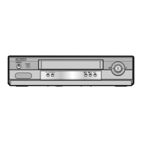
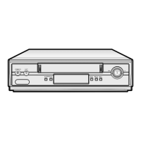
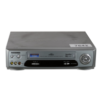
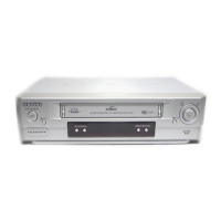
Illustrates the main cabinet components and their assembly structure.

Mechanical Parts Identification (Top and Bottom)

Detailed list and diagrams of mechanical parts for the top and bottom views of the unit.

Comprehensive Electrical Component Listing

Circuit Schematic Diagrams

SMPS Schematics (230V and Free Voltage)

Circuit diagrams for the Switched-Mode Power Supply in both 230V and free voltage configurations.

Power Drive and System Control Schematics

Circuit diagrams detailing the Power Drive section and the System Control/Servo functions.

Audio/Video, Secam, and Input/Output Schematics

Circuit diagrams for the Audio/Video processing, Secam system, and Input/Output interfaces.

Remote Control Schematics

Circuit diagrams for the Multi-TV and VCR-only remote controls, showing button mapping.

Related product manuals