EasyManua.ls Logo

Samsung SV-5000W Service Manual

Samsung SV-5000W
103 pages
To Next Page IconTo Next Page
Page #1 background imageLoading...
Page #1 background image
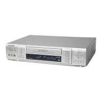
VIDEO CASSETTE RECORDER
SV-7000W
SV-5000W
SERVICE
1. Precautions
2. Reference Information
3. Product Specifications
4. Disassembly and Reassembly
5. Troubleshooting
6. Alignment and Adjustment
7. Exploded View and Parts List
8. Electrical Parts List
9. Block Diagram
10. PCB Diagrams
11. Wiring Diagram
12. Schematic Diagrams
Manual
VIDEO CASSETTE RECORDER CONTENTS
For mechanical disassembly and adjustment, refer to the “Mechanical Manual” (DX-9R AC68-00001A).
SERVICE MANUAL SV-7000W/SV-5000W
ELECTRONICS
© Samsung Electronics Co., Ltd. SEP. 1999
Printed in Korea
AC68-00434A
SV-7000W
SV-5000W

Other manuals for Samsung SV-5000W

Question and Answer IconNeed help?

Do you have a question about the Samsung SV-5000W and is the answer not in the manual?

Samsung SV-5000W Specifications

General IconGeneral
BrandSamsung
ModelSV-5000W
CategoryVCR
LanguageEnglish

Summary

Precautions

General Safety Precautions

General safety guidelines for handling and operating the unit.

Product Specifications

Disassembly and Reassembly

Cabinet Removal Procedures

Step-by-step instructions for removing various cabinet parts.

Troubleshooting

Alignment and Adjustment

Mechanical Adjustment Procedures

Step-by-step procedures for mechanical alignment and settings.

Specific Adjustment Procedures

Detailed steps for head switching, NTSC skew, and NVRAM settings.

Electrical Parts List

Block Diagram

Wiring Diagram

Schematic Diagrams

S.M.P.S. Schematic

Schematic diagram for the Switched-Mode Power Supply.

Power Schematic

Schematic diagram for the power supply section.

System Control/Servo Schematic

Schematic diagram for the system control and servo circuits.

Audio/Video Schematic

Schematic diagram for the audio and video processing circuits.

Hi-Fi Schematic

Schematic diagram for the Hi-Fi audio section.

TM-Block Schematic

Schematic diagram for the TM-Block.

Related product manuals