EasyManua.ls Logo

Samsung VP-L150 User Manual

Samsung VP-L150
144 pages
To Next Page IconTo Next Page
Page #1 background imageLoading...
Page #1 background image
8mm CAMCORDER
VP-L100/VP-L150
SCL100/SCL150
SERVICE
1. Precautions
2. Reference Information
3. Product Specifications and
Comparison Chart
4. Disassembly and Reassembly
5. Alignment and Adjustment
6. Exploded View and Parts List
7. Electrical Parts List
8. Block Diagrams
9. PCB Diagrams
10. Wiring Diagram
11. Schematic Diagrams
Manual
8mm CAMCORDER
CONTENTS
For mechanical disassembly and adjustment, refer to the “Mechanical Manual”
(DE-6 AD68-30200A).
A
Question and Answer IconNeed help?

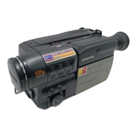
Do you have a question about the Samsung VP-L150 and is the answer not in the manual?

Samsung VP-L150 Specifications

General IconGeneral
TypeCamcorder
Recording MediaMini DV
LCD Screen Size2.5 inches
Battery TypeLithium-ion
Video Resolution720 x 480
Effective Pixels680, 000
InterfaceIEEE 1394 (FireWire)
Image Sensor1/6" CCD

Summary

Precautions

Product Specifications

Disassembly and Reassembly

4-1 Cabinet and PCB

Procedure for removing the main cabinet and PCB assemblies.

Alignment and Adjustment

5-1 Mechanical Adjustment

Procedure for performing mechanical alignment for linearity.

5-2 Camera Section Adjustment

Adjustments related to the camera's image and signal processing.

5-3 VCR Section Adjustment

Adjustments for the Video Cassette Recorder section.

Block Diagrams

8-1 Overall Block Diagram (Camera)

High-level block diagram of the camera section.

8-2 Overall Block Diagram (VCR)

High-level block diagram of the VCR section.

Schematic Diagrams

11-1 DC/DC Converter Schematic

Schematic diagram of the DC/DC converter circuit.

11-2 System Control/Servo Schematic

Schematic diagram for the system control and servo circuits.

Related product manuals