Disassembly and Reassembly
Samsung Electronics
1-7
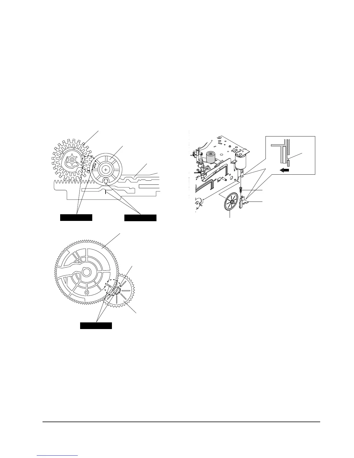
1-2-7 Assembly of Gear FL Cam,
Gear Joint 1, 2
1) Be sure to align dot mark of Gear Joint 1 Πwith
dot mark of Gear Joint 2 ´ as shown Fig. 1-10
(Refer to Timing Point 1), confirm the Timing Point
2 of the Gear Joint 2 ´ and Slider Cam ˇ.
2) Align the Gear FL Cam ¨ with the Gear Worm
Wheel Post as shown detail drawing. (Refer to
Timing Point 3)
ΠGEAR JOINT 1
´ GEAR JOINT 2
ˇ SLIDER CAM
TIMING POINT 1
¨ GEAR FL CAM
GEAR WORM WHEEL
POST
TIMING POINT 2
TIMING POINT 3
1-2-8 Holder Worm, Gear Worm,
Gear Worm Wheel Removal
1) Release the Hook [A] in the direction of arrow and,
remove the Holder Worm Œ.
2) Remove the Gear Worm ´.
3) Remove the Gear Worm Wheel ˇ. (After remov-
ing the Gear FL Cam as shown Fig. 1-9)
Note : Secure the Hook [A] after installing the Holder
Worm Œ.
ΠHOLDER WORM
´ GEAR WORM
HOOK [A]
ˇ GEAR WORM WHEEL
Fig. 1-10 Assembly of Gear FL Cam, Gear Joint 1,2
Fig. 1-11 Holder Worm, Gear Worm,
Gear Worm Wheel Removal


 To Next Page