M
Michelle SimpsonAug 7, 2025
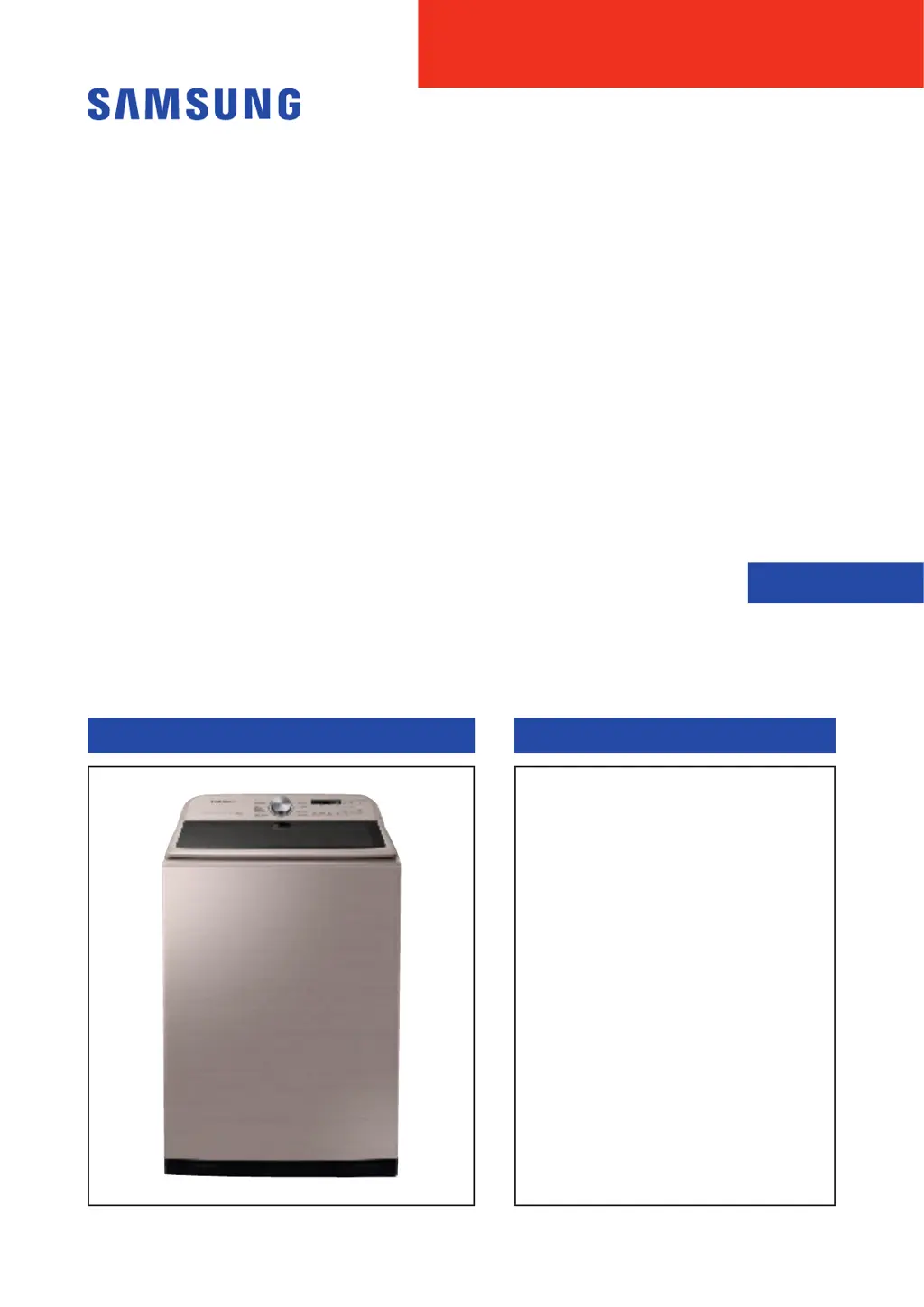
What to do if my Samsung WA7750M is not draining?
- LLatoya FrancisAug 7, 2025
If your Samsung Washer isn't draining properly, start by checking the drain hose for any clogs. Also, inspect the water pump terminal for any disconnections or obstructions such as rubber bands, bills, cotton, hair pins or coins inside the drain pump assembly and remove any obstructions. If the pump motor impeller is damaged, it will need to be replaced. Ensure the correct voltage is being supplied to the parts. If freezing is the cause, allow the machine to thaw before attempting to use it.