EasyManua.ls Logo

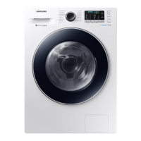
Samsung WD80J6410AW/EU User Manual

Samsung WD80J6410AW/EU
54 pages
To Next Page IconTo Next Page
Page #1 background imageLoading...
Page #1 background image
WASHING MACHINE (DRUM) CONTENTS
SERVICE
Manual
WASHING MACHINE
DRUM TYPE
Basic Model : WD80J6410AW/EU
(WD6000J)
Model Name : WD8*K64****
WD9*K64****
WD10K64****
WD11K64****
(WD6500K)
Model Code : WD7*K6*****/X
WD8*K6*****/X
WD9*K6*****/X
WD10K6*****/X
WD11K6*****/X
(WD6500K)
1. Safety Instructions
2.FeaturesandSpecications
3. Disassembly and Reassembly
4. Troubleshooting
5. PCB Diagram
6. Wiring Diagram
7. Reference
WD6500K_7-8-9-11kg_1400rpm-SM.indb 1 2018/11/9 9:52:43

Questions and Answers:

Samsung WD80J6410AW/EU Specifications

General IconGeneral
BrandSamsung
ModelWD80J6410AW/EU
CategoryWasher
LanguageEnglish

Summary

1. SAFETY INSTRUCTIONS

1-1. SAFETY INSTRUCTIONS FOR SERVICE ENGINEERS

Essential safety guidelines for service engineers to prevent accidents and hazards during product maintenance and repair.

2. FEATURES AND SPECIFICATIONS

2-1. FEATURES

Detailed overview of common and optional features, including drying, diamond drum, air refresh, and volt control.

2-2. SPECIFICATIONS

Technical specifications covering dimensions, capacity, water volume, power consumption, and spin speed for various models.

2-3. COMPARING SPECIFICATIONS WITH EXISTING MODELS

Comparative analysis of the WD6500K model's specifications against other Samsung washing machine models.

2-4. OPTIONS SPECIFICATIONS

List of optional items with their part codes, quantities, and specific model applicability, such as hoses and fasteners.

3. DISASSEMBLY AND REASSEMBLY

3-1. TOOLS FOR DISASSEMBLY AND REASSEMBLY

Lists essential tools like box drivers, spanners, and pliers required for the safe disassembly and reassembly of washing machine components.

3-2. STANDARD DISASSEMBLY DRAWINGS

Step-by-step illustrated guide for disassembling key parts such as the top cover, control panel, and housing drawer.

4. TROUBLESHOOTING

4-1. CHECK MODES

Details common diagnostic check modes (e.g., Water Level Sensor, Motor Check) and their associated causes for troubleshooting.

4-2. CORRECTIVE ACTIONS FOR EACH CHECK CODE

Provides specific corrective actions and troubleshooting steps for various check codes, including voltage checks and component replacements.

5. PCB DIAGRAM

5-1. MAIN PCB (DD)

Diagram showing component layout and connector functions for the main Printed Circuit Board (PCB) of the washing machine.

5-2. CIRCUIT DIAGRAMS OF MAIN PARTS FOR MAIN PCB (DD)

Circuit diagrams illustrating signal flow and connections for key components linked to the main PCB, such as fan motor and door signals.

5-3. INVERTER PCB

Layout and connector identification for the Inverter PCB, responsible for motor control and power management.

5-4. CIRCUIT DIAGRAMS OF MAIN PARTS(INVERTER PCB)

Circuit diagrams for main parts connected to the Inverter PCB, detailing motor signals and communication lines.

5-5. SUB PCB

Diagram and component overview of the Sub PCB, which manages user interface elements like the display and buzzer.

5-6. DETAILED DESCRIPTIONS OF CONTACT TERMINALS FOR SUB PCB

Explanation of contact terminals on the Sub PCB, including their functions for program writing, display, and touch sensing.

7. REFERENCE

7-1. WD6500K PROJECT NAME

Explains the structure of the WD6500K model name and BOM code, detailing capacity, RPM, and color coding.

6. WIRING DIAGRAM

6-1. WIRING DIAGRAM

Schematic electrical wiring diagram showing connections between major components like main PCB, sub PCB, motor, and sensors.

Related product manuals