Do you have a question about the Samsung WF405 A2 Series and is the answer not in the manual?
Technical safety warnings and liability disclaimer for service personnel.
Procedure to test components with the washing machine powered off.
Procedures for diagnostic checks and testing with the washing machine powered on.
Steps to check door lock switch resistance and connectivity.
Procedure for checking the water level sensor frequency and connections.
Instructions for checking water valve resistance and voltage.
Method to check resistance across the drain motor terminals.
Procedure for measuring drum motor terminal resistance.
Causes and corrective actions for water level sensor faults.
Troubleshooting steps for washing motor and hall sensor faults.
Diagnosing low water pressure issues and supply faults.
Corrective actions for drain pump faults, blockages, and freezing.
Troubleshooting electronic control and main relay switch faults.
Diagnosing issues related to door status, locking, and unlocking.
Troubleshooting washing heater and temperature sensor faults.
Identifying and fixing water leakage problems in various parts.
Diagnosing overflow issues including hose problems and freezing.
Corrective actions for faulty washing and dry temperature sensors.
Addressing issues caused by unbalanced loads or motor sensor faults.
Further troubleshooting for heater and temperature control problems.
Additional steps to identify and resolve water leakage points.
Understanding notifications for excessive foaming during cycles.
Troubleshooting PBA and data errors, checking connections.
Diagnosing microcontroller failures and replacing the PCB.
Addressing problems where the door will not lock or unlock.
Troubleshooting issues with the spin cycle and excessively wet loads.
Resolving non-responsive controls and problems with excessive suds.
Diagnosing and fixing water leaks and failures to drain.
Troubleshooting operational noise, vibration, and water filling problems.
Diagram detailing connectors and their functions on the Sub PCB.
Diagram showing connectors and their pin assignments on the Main PCB.
Schematic diagram illustrating connections between components.
Key for identifying wire colors used in the schematic.
| Capacity | 4.0 cu. ft. |
|---|---|
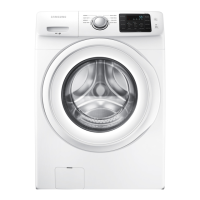
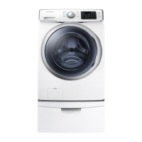
| Color | White |
| Number of Wash Cycles | 9 |
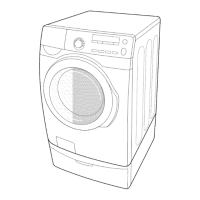
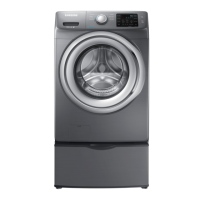
| Washer Type | Front Load |
| Energy Star Certified | Yes |
| Voltage | 120V |
| Wash Cycles | Normal, Heavy Duty, Delicates, Quick Wash, Rinse+Spin |