Do you have a question about the Samsung XA067T and is the answer not in the manual?
Explains warning symbols, grounding, and electrical safety precautions.
Outlines personal protection and equipment safety guidelines for installation and operation.
Provides essential instructions and warnings for safe installation procedures.
Illustrates the front view during the unpacking process with sequential steps.
Shows the side view during the unpacking process with sequential steps.
Instructions for safely placing the cabinet to prevent module damage.
Detailed technical specifications for the outdoor LED display models.
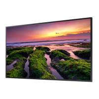
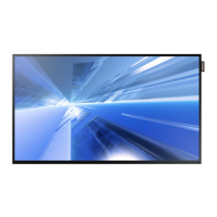
Visual representation of the product's external design and dimensions.
Illustrates the internal layout and components of the cabinet.
Identifies key components like modules, power supply, and receiving cards.
Diagram showing connections between PC, sending box, and LED display.
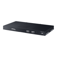
Visual catalog of included accessories with part numbers.
Catalog of spare parts available for the product with images and codes.
Bill of Materials listing all parts, their codes, specifications, and units.
Detailed BOM for service and repair purposes.
Solutions for issues like screen not lighting up or blinking.
Troubleshooting steps for cabinet issues like not lighting up or blinking.
Guidance for resolving issues with individual display modules.
Covers support structure, ground stability, environmental conditions, and installation tools.
Details on power system, cabling, grounding, and lightning protection.
Illustrates connections between PC, sending box, and LED display.
Details on connecting AC power cables, including cascade specifications.
Instructions for connecting signal cascade cables, specifying types and capacity.
Provides a sample drawing for cabinet installation arrangement.
Step-by-step guide for installing the NovaLCT software.
Introduces the NovaLCT interface and login process.
Overview of system and settings menus within NovaLCT.
Guide to configuring the LED display using system configuration files.
Adjusting color settings including factory, space, and temperature.
Steps for adjusting screen brightness and gamma settings.
Functions for controlling screen display: Black Out, Freeze, Normal, Self Test.
How to view hardware status, time, communication ports, and program versions.
Online calibration process for LED displays using NovaCLB software.
Tools for adjusting and managing calibration coefficients for better display performance.
Steps to set calibration coefficients for a new receiving card.
How to adjust color coefficients for specific areas of the display.
Process for setting calibration coefficients for a new LED module.
Applying adjustment operations from one area to other areas.
Options to erase all coefficients or reload saved ones.
Resetting calibration coefficients for the screen or specific areas.
Monitoring status of hardware components like cards, temperature, and fan.
Procedure for cleaning outdoor LED display screens to maintain performance.
Discusses factory and site calibration for color uniformity.
Detailed service steps for replacing components like modules, power supplies, and boards.
Steps for replacing display modules from front and back service access.
Steps for replacing the power supply unit from front and back service access.
Steps for replacing the HUB board from front and back service access.
Steps for replacing the receiving card from front and back service access.
Steps for replacing the air switch from front and back service access.
Steps for replacing various cables like power, signal, flat, and DC.
Details customer responsibilities and costs for paid service calls.
Information regarding product and accessory disposal and recycling.
| Brand | Samsung |
|---|---|
| Model | XA067T |
| Category | Digital Signage |
| Language | English |