14
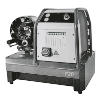
Setting the crimping diameter
From the crimping diameter
chart, delivered together with the
machine, you can see the die
set numbers and the
corresponding crimping ranges.
The upper section of the chart
shows the corresponding dial
position for each crimping
iameter in the columns.
d
Crimping diameters in the grey
zone of the chart are not
recommended to be used with
he die set in question.
t
The crimping diameter dial has
been calibrated at the factory so
that when the dial is set at 0.0,
the resulting diameter will be the
minimum diameter of the die set
installed, i.e. with die set No 20-
16 the crimping diameter will be
16 mm, No 20-19 gives a
diameter of 19 mm etc. Each full
turn clockwise of the adjusting
knob of the dial will add 1 mm to
the crimping diameter. Each
division on the measuring scale
corresponds to 1/100 mm.
EXAMPLE:
Manufacturer has
specified a crimping
diameter of 20.6 mm for
the fitting. Select die set
No 20-19 (min crimping
diameter 19 mm)
according to the die
chart. Turn the dial to
position 1.60 (upper
scale 1, lower 60). This
setting will give the
crimping diameter
20.6 mm (19 + 1.6 mm).
The machine has been
calibrated at the factory
with 40 bar pressure.
This means that when
you are
crimping a fitting
requiring 40 bar
pressure, the measuring
scale of the crimping
diameter dial provides
an accuracy of +/- 0.1
mm (possible elastic
recovery of the fitting not regarded).
When fittings requiring higher pressure are crimped, the crimping diameter may become larger than the
value on the scale due to machine deflections. Then the crimping diameter has to be corrected by changing
the scale value.
The crimping diameter chart P20
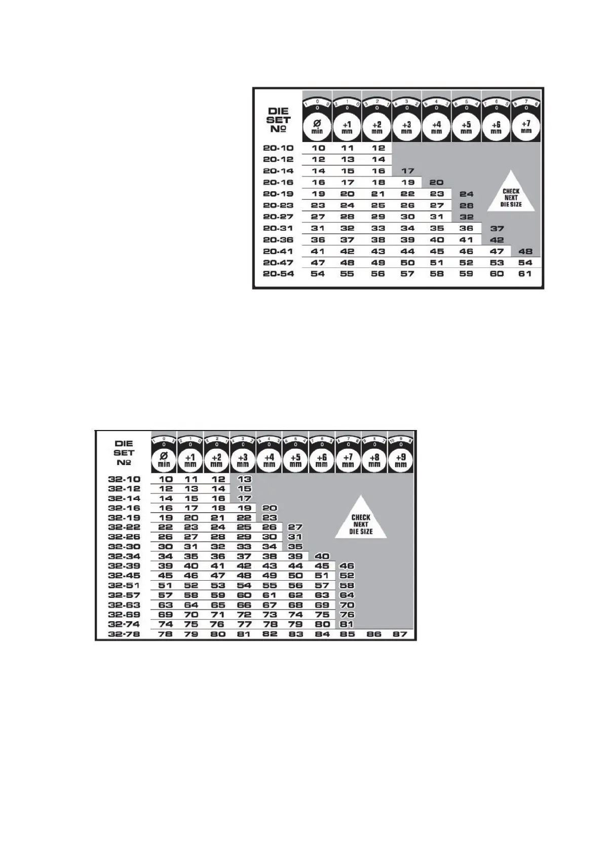
The crimping diameter chart P32