INSTRUCTION SHEET
716-600
Page 13 of 24
February 11, 2002
S&C ELECTRIC COMPANY
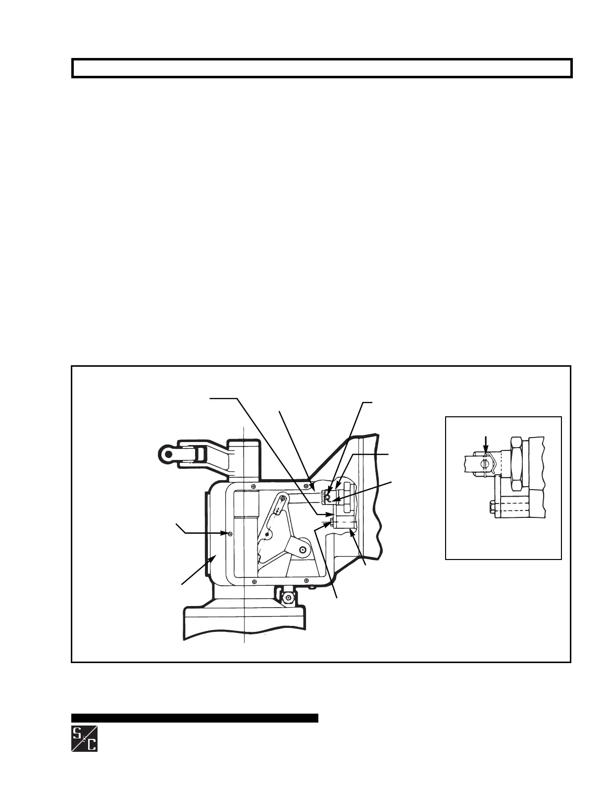
Transition box
INTERRUPTER REPLACEMENT ON MODELS 2010, 2015, AND 2040 — Continued
Pin
retaining
clip
Operating rod link
Stop bracket (marked with a
black/yellow striped label)
Six ⁵⁄₁₆—18³⁄₄ hex-head
stainless-steel cap screws for
access cover (removed)
Spacer (marked with a black/yellow
striped label)
Circuit-Switchers rated
161 kV and 230 kV
Connecting pin
Coupling
Pin retaining clip
Circuit-Switchers rated 69 kV through 138 kV
⁵⁄₁₆—182¹⁄₄ hex-head
stainless-steel screw
Figure 10. Transition box on Model 2010 and Model 2015 Series 2000 Circuit-Switchers rated 69 kV through 138 kV. Model
2040 is similar. Inset illustrates pin retaining clip used on Circuit-Switchers rated 161 kV and 230 kV.
shields for the interrupter pressure-relief device and low-
gas-pressure indicator, furnished with the replacement
interrupter (in a separate box), using two ¹⁄₂—131¹⁄₄
hex-head stainless-steel cap screws furnished. See
Figure 11.
Step 20
Remove the six ⁵⁄₁₆—18³⁄₄ hex-head stainless-steel cap
screws used to attach the access cover to the side of the
transition box on the insulating support column. See
Figure 10. Remove the cover and place it and the
hardware on a clean surface. They will be re-used in
Step 31.
Step 21
Prepare the interrupter for removal as follows. See
Figure 10.
(a) Attach the spare stop bracket (marked with a
black/yellow striped label) and spacer (marked with a
black/yellow striped label) to the interrupter using the
⁵⁄₁₆—182¹⁄₄ hex-head stainless-steel screw fur-
nished. (These items are included with the replace-
ment interrupter, in a separate box.) Hand-tighten the
screw.
(b) Remove the pin retaining clip and connecting pin
which attach the coupling to the operating rod link.
Discard the connecting pin and pin retaining clip.
(c) Now securely tighten the ⁵⁄₁₆—182¹⁄₄ hex-head
stainless-steel screw.
Step 22
Remove the four ¹⁄₂—13 stainless-steel hex nuts and
Belleville washers which attach the interrupter to the
transition box. Also remove the four ¹⁄₂—131¹⁄₄ hex-
head galvanized steel cap screws and flat washers (for
Circuit-Switchers rated 69 kV) or the four ⁵⁄₈—111¹⁄₄
hex-head galvanized steel cap screws and flat washers
(for Circuit-Switchers rated 115 kV through 230 kV)
which are used to attach the terminal pad to the support
insulator. See Figure 11. Retain the hardware for re-use in
Step 29.
 Loading...


