S&C ELECTRIC COMPANY
716-600
INSTRUCTION SHEET
Page 16 of 24
February 11, 2002
S&C Series 2000 Circuit-Switchers Interrupter Replacement
Outdoor Transmission (69 kV through 230 kV)
INTERRUPTER REPLACEMENT ON MODELS 2010, 2015, AND 2040 — Continued
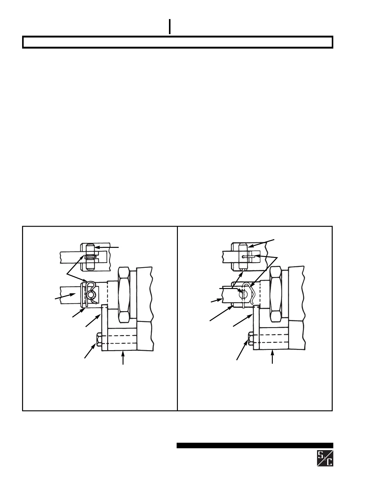
Connecting pin
(with groove)
Pin retaining
clip
Operating
rod link
Stop bracket (marked
with a black/yellow
striped label)
⁵⁄₁₆—182¹⁄₄
hex-head stainless-steel screw
Spacer (marked with
a black/yellow striped
label)
Connecting pin
(with cross-hole)
Operating
rod link
Stop bracket (marked
with a black/yellow
striped label)
⁵⁄₁₆—182¹⁄₄
hex-head stainless-steel
screw
Spacer (marked with
a black/yellow striped
label)
Slot
(coincides with
cross-hole)
Circuit-Switchers rated 69 kV through 138 kV
Circuit-Switchers rated 161 kV and 230 kV
Pin retaining clip
Coupling
Coupling
Step 30
For interrupters with the remote gas-density monitor
option, see “Installing the Transmitter” on page 18.
For Circuit-Switchers rated 69 kV through 138 kV:
Insert the connecting pin retained from Step 28 into the
coupling and operating rod link. See Figure 13 (left). It
will be necessary to loosen the
⁵⁄₁₆
—18
2
¹⁄₄
hex-head
stainless-steel screw indicated in Figure 13 (left) and
withdraw it approximately
¹⁄₈
inch, so that the connect-
ing pin can be inserted. Do not remove the screw at this
time. Now insert the pin retaining clip retained from Step
28 as indicated in Figure 13 (left). Make sure that the clip
is positioned as shown. Finally, remove and discard the
⁵⁄₁₆—182¹⁄₄ hex-head stainless-steel screw, stop bracket
(marked with a black/yellow striped label), and spacer
(marked with a black/yellow striped label) illustrated in
Figure 13 (left).
For Circuit-Switchers rated 161 kV and 230 kV:
Insert the connecting pin retained from Step 28 into the
coupling and operating rod link. See Figure 13 (right). It
will be necessary to loosen the
⁵⁄₁₆
—18
2
¹⁄₄
hex-head
stainless-steel screw indicated in Figure 13 (right) and
withdraw it approximately
¹⁄₈
inch, so that the connect-
ing pin can be inserted. Do not remove the screw at this
time. Use a screwdriver blade in the slot at the end of the
connecting pin to align the cross-hole in the connecting
pin with the cross-hole in the operating rod link. Now
insert the pin retaining clip retained from Step 28 as indi-
cated in Figure 13 (right). Make sure that the clip is posi-
tioned as shown. Finally, remove and discard the
⁵⁄₁₆—182¹⁄₄ hex-head stainless-steel screw, stop
bracket (marked with a black/yellow striped label), and
spacer (marked with a black/yellow striped label) illus-
trated in Figure 13 (right).
Figure 13. Coupling replacement interrupter.
 Loading...


