INSTRUCTION SHEET
716-600
Page 21 of 24
February 11, 2002
S&C ELECTRIC COMPANY
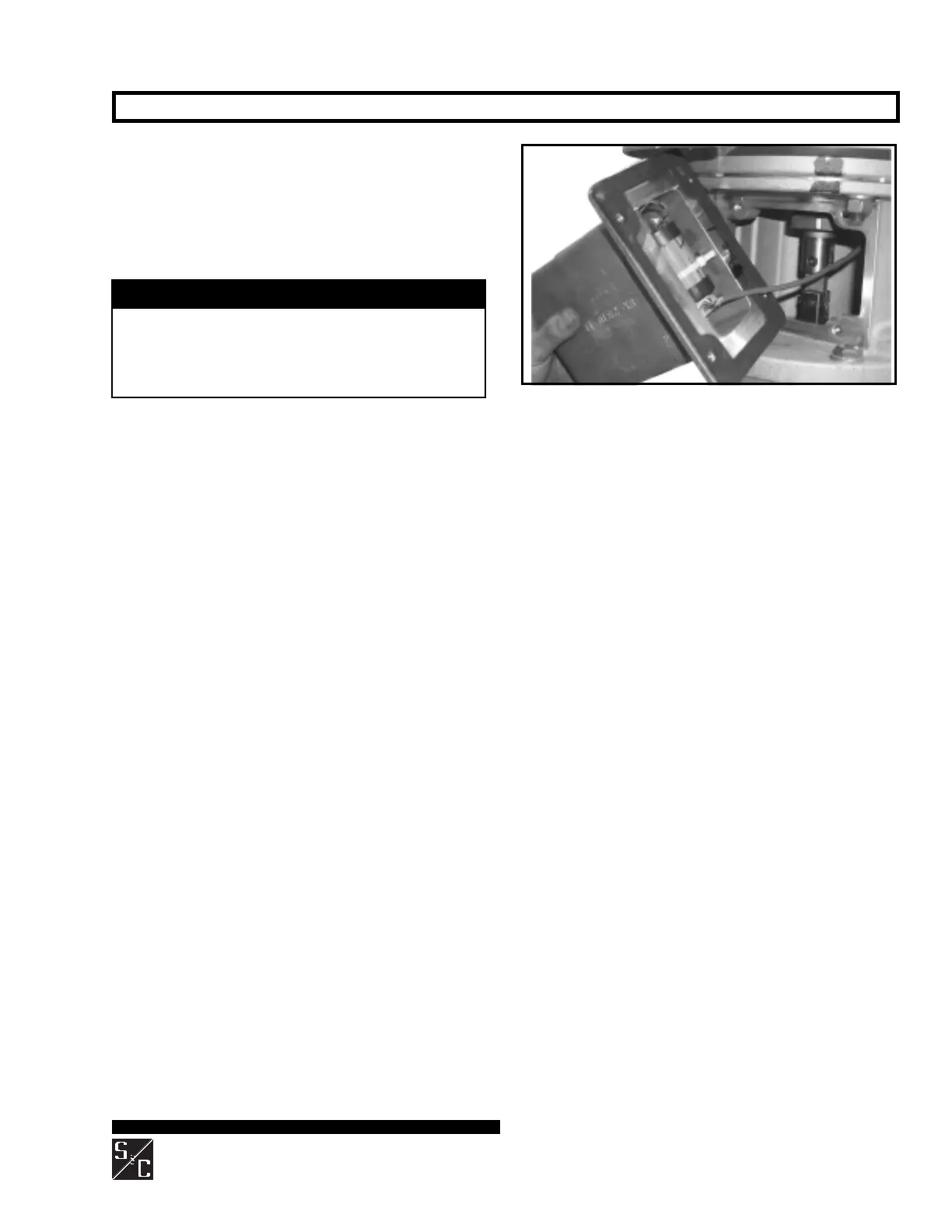
Step 44
Using the mounting hardware saved from Step 38, reat-
tach the transmitter to the transition box, making sure
that the black antenna cover faces the ground. See Figure
19. Repeat Steps 37 through 44 for each interrupter to be
replaced. Retain the jumper for future use, in the pocket
on the operator enclosure door.
NOTICE
Save the shorting plugs, and install them on the
replaced interrupters. When replacing an interrupter
with the remote gas-density monitor option, ship the
replaced transmitter to S&C Electric Company along
with the replaced interrupter.
INTERRUPTERS WITH THE REMOTE GAS-DENSITY MONITOR OPTION — Continued
Figure 19. Reattach the transmitter to the transition box
after making the battery and sensor cable connections.
 Loading...


