INSTRUCTION SHEET
716-600
Page 9 of 24
February 11, 2002
S&C ELECTRIC COMPANY
INTERRUPTER REPLACEMENT ON MODELS 2020, 2025, AND 2030 — Continued
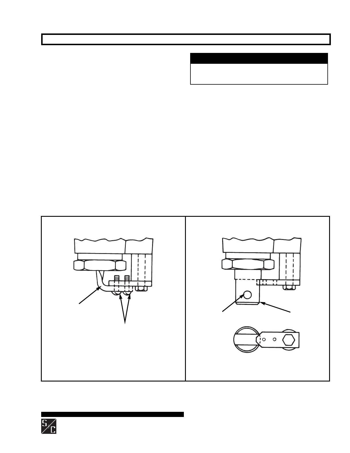
Operating-rod holding
bracket (marked with a
black/yellow striped label)
Operating rod in shipping position
Operating rod in fully open position
#10–32 screws
Coupling
Connecting pin
Figure 7. Preparing replacement interrupter for attachment to insulating support column.
Step 9
Attach a lifting sling to the lifting bracket on the
replacement interrupter. Then carefully lift the interrupter
somewhat higher than the top of the transition box on the
insulating support column. Use care to avoid damaging
the exposed coupling.
Step 10
Prepare the replacement interrupter for attachment to the
insulating support column as follows:
(a) Remove and discard the two #10–32 screws which
connect the operating-rod holding bracket (marked
with a black/yellow striped label) for shipment. See
Figure 7 (left).
(b) Pull the holding bracket to move the operating rod to
its fully open position. See Figure 7 (right).
(c) Remove the connecting pin and pin retaining clip used
to attach the holding bracket to the coupling. Retain
the connecting pin and pin retaining clip for re-use in
Step 11(d), but discard the holding bracket.
NOTICE
The operating rod is under pressure; when the two
screws are removed, the holding bracket may move
about ¹⁄₂ inch.
 Loading...


