S&C ELECTRIC COMPANY
s
716-501
INSTRUCTION SHEET
Page 10 of 26
August 12, 2002
S&C Series 2000 Circuit-Switchers Model 2010 — With Horizontal Interrupters and
Outdoor Transmission (69 kV through 230 kV) Vertical-Break Power-Operated Disconnect
INSTALLATION
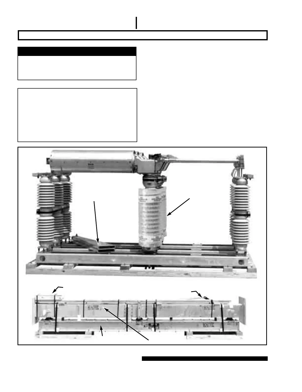
Pole-unit
Support arms
Mounting pedestal
Miscellaneous operating-mechanism
components and hardware
Cross base
Interphase pipe assembly and
interphase drive link
Figure 2. Typical shipment of Model 2010 Series 2000 Circuit-Switcher. Operator is shipped on a separate skid; see Figure 5.
BOLTED AND PINNED CONNECTIONS
A typical bolted connection for field assembly
requires a flat washer under the cap screw and one
under the nut. In instances where self-locking hex
nuts are specified, it is essential that the threads of
the associated cap screws be lubricated with a gen-
eral-purpose grease, to facilitate tightening. All pins
used in the field assembly should also be lubricated
to facilitate insertion.
Step 1
Cut the steel straps that bind the mounting pedestals to
the cross base, the straps that bind the container of mis-
cellaneous operating-mechanism components and hard-
ware, and the straps that bind the pole-units. Also remove
the wood bracing between the pole-unit terminal pads.
See Figure 2. For Circuit-Switchers rated 161 kV and
230 kV: Remove the lifting angles attached to the pole-unit
channel bases; retain these lifting angles and associated
hardware for re-use in Step 13.
Ç
CAUTION
Do not remove the containers from the interrupters,
or the plastic bubble-wrap from the insulating sup-
port columns, until the installation has been
completed.
 Loading...


