S&C ELECTRIC COMPANY
s
INSTRUCTION SHEET
716-501
Page 21 of 26
August 12, 2002
INSTALLATION — Continued
(c) Pry the container-halves apart with a screwdriver. The
upper container-half can now be removed and dis-
carded—slotted holes are provided so that a rope or
lifting sling can be attached and the container-half
more conveniently lowered to the ground.
(d) Now remove and discard the ³⁄₈—16⁷⁄₈ hex-head
cap screw and flat washer which attach the lower con-
tainer-half to the coupling end casting of the inter-
rupter, and the ³⁄₈—16⁷⁄₈ hex-head cap screw and
flat washer which attach the lower container-half to
the indicator end casting of the interrupter. Then dis-
card this container-half.
(e) Finally, remove and discard the foam-core inner liner
wrapped around the interrupter.
Now remove the shield for the pressure-relief
device and low-gas-pressure indicator.
Step 25
Remove and discard the plastic bubble-wrap from each
insulating support column.
Step 26
Perform the following set-up procedure on the operator.
See Figure 15.
(a) To avoid accidentally energizing the operator after the
external connections have been completed, open the
control-source disconnect switch.
(b) Loosen the clamps on the inside of the side access
door, open the side access door, and remove the
blocking from the motor contactors.
(c) Mark the conduit-entrance location for the control-cir-
cuit wiring on the conduit entrance plate in the bottom
of the operator enclosure. Then remove the plate and
cut out the necessary opening. Apply the sealing com-
pound furnished, replace the plate, and make up the
entrance fittings. Verify that the entrance fittings are
properly sealed to prevent water ingress.
(d) Connect the external control-circuit wiring (including
the space-heater source leads) to the terminal blocks
at the bottom of the enclosure, in accordance with the
wiring diagram furnished. Observe correct polarity on
dc-control-voltage models. Trip-circuit conductors
and motor-and-closing circuit conductors must be
adequately sized for the ampacities indicated on the
wiring diagram.
Ç
CAUTION
Unauthorized changes should not be made in the
wiring of the operator. Should a control-circuit revi-
sion appear desirable, it should be made only on the
authority of a revised wiring diagram which has been
approved by both the user and S&C Electric Com-
pany.
Do not apply control voltage to the operator at this
time!
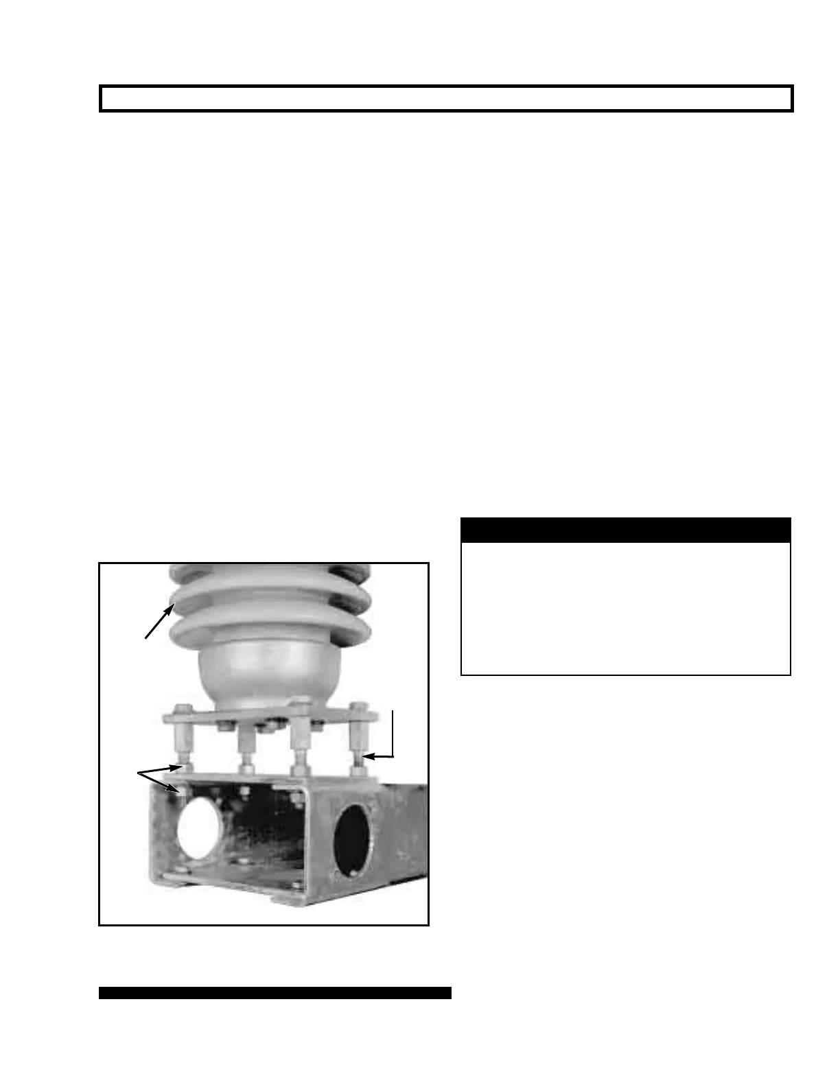
Figure 14. Adjusting leveling-screw locknuts.
Jaw-contact
support
insulator
Locknuts
Leveling
screw
 Loading...


