S&C Instruction Sheet 716-504 25
Installation
Step 24
Check for proper blade closure at the center
pole-unit marked “Pole 2.” With a pull-out force
of approximately 40 pounds applied at the
position indicated in Figure24 on page 23, the
blade deection should be no more than ½-inch.
If necessary, loosen the locknuts at the top
and bottom of the vertical operating pipe, and
rotate the pipe counterclockwise (as viewed
from the top) to increase blade travel. Tighten
the locknuts. See Figure25 on page 24.
Step 25
Check for proper blade closure at the two
outboard pole-units—marked “Pole 1” and
“Pole 3.” With a pull-out force of approximately
40 pounds applied at the position indicated in
Figure24 on page 23, the blade deection should
be no more than ½ inch. If necessary, loosen
the four ½–13×1½-inch hex-head stainless
steel cap screws that attach the blade clamp
to the transition box, and rotate the blade
counterclockwise (as viewed from the top) to
increase blade travel. Tighten the cap screws.
See Figure29.
Step 26
Use the manual charging handle furnished with
the operator to check the functioning of the
disconnect power train, as follows. Refer to
Figure30 on page 26 and Figure 31 on page 27.
(a) Open the access shutter and place the
manual charging handle on the manual
charging shaft.
(b) Rotate the shaft, clockwise only, until a
rm resistance is felt. At this point, the
disconnect blades should be open ap-
proximately 90 degrees. If the discon-
nect blades are not open to this extent,
loosen the locknuts at the top and bot-
tom of the vertical operating pipe, and
rotate the pipe clockwise (as viewed
from the top) to increase blade travel,
then tighten the locknuts. See Figure25
on page 24.
(c) Remove the manual charging handle
from the manual charging shaft and
replace it in its holder on the operator
door. See Figure30 on page 26.
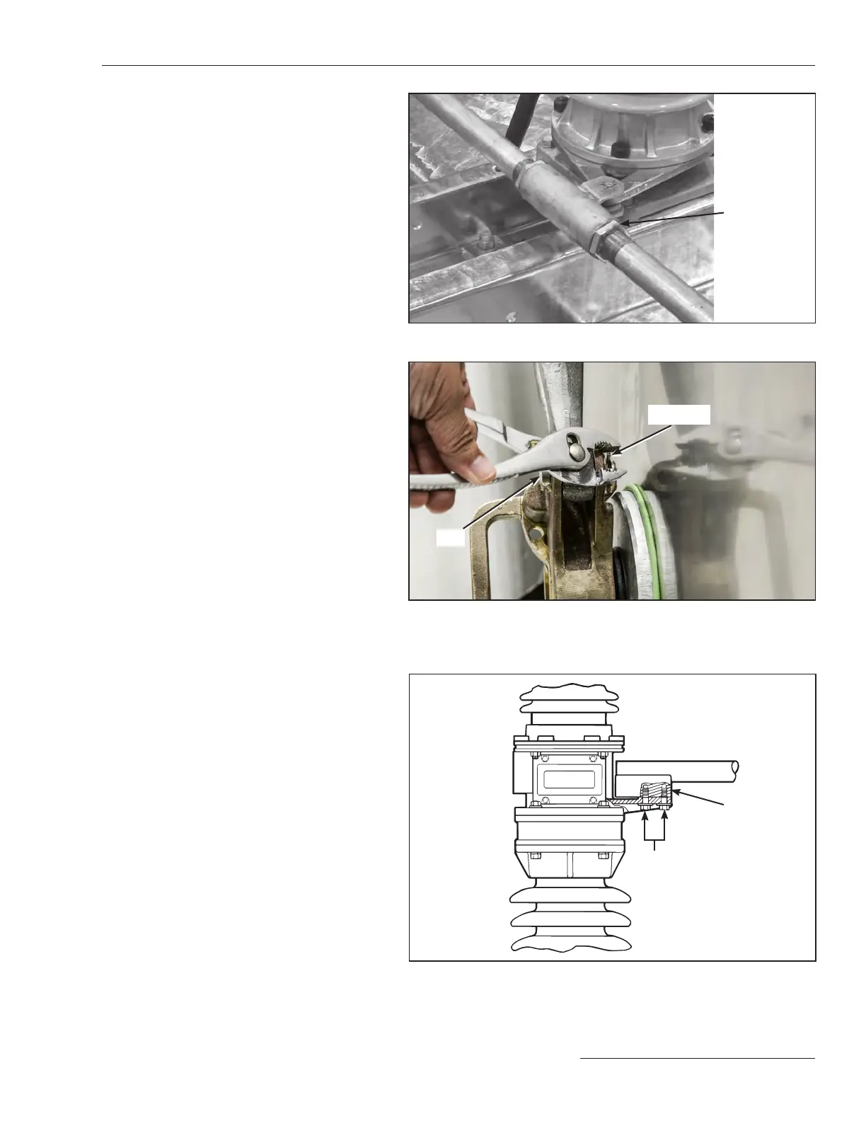
Figure 27. Loosen locknut and rotate to adjust the pipe length.
Figure 28. The “C ”-shaped clevis on rear of operator connects the vertical
operating pipe to the back of the operator. Attach the "C"-shaped clevis
to the operator using a ⅝-inch steel pin and X-washer.
Figure 29. Adjust the blade at outboard pole-unit to attain specified blade
deflection.
Blade clamp
Locknut
½ –131½-inch
hex-head
stainless-steel screws
X-washer
Pin
 Loading...


