26 S&C Instruction Sheet 716-504
Installation
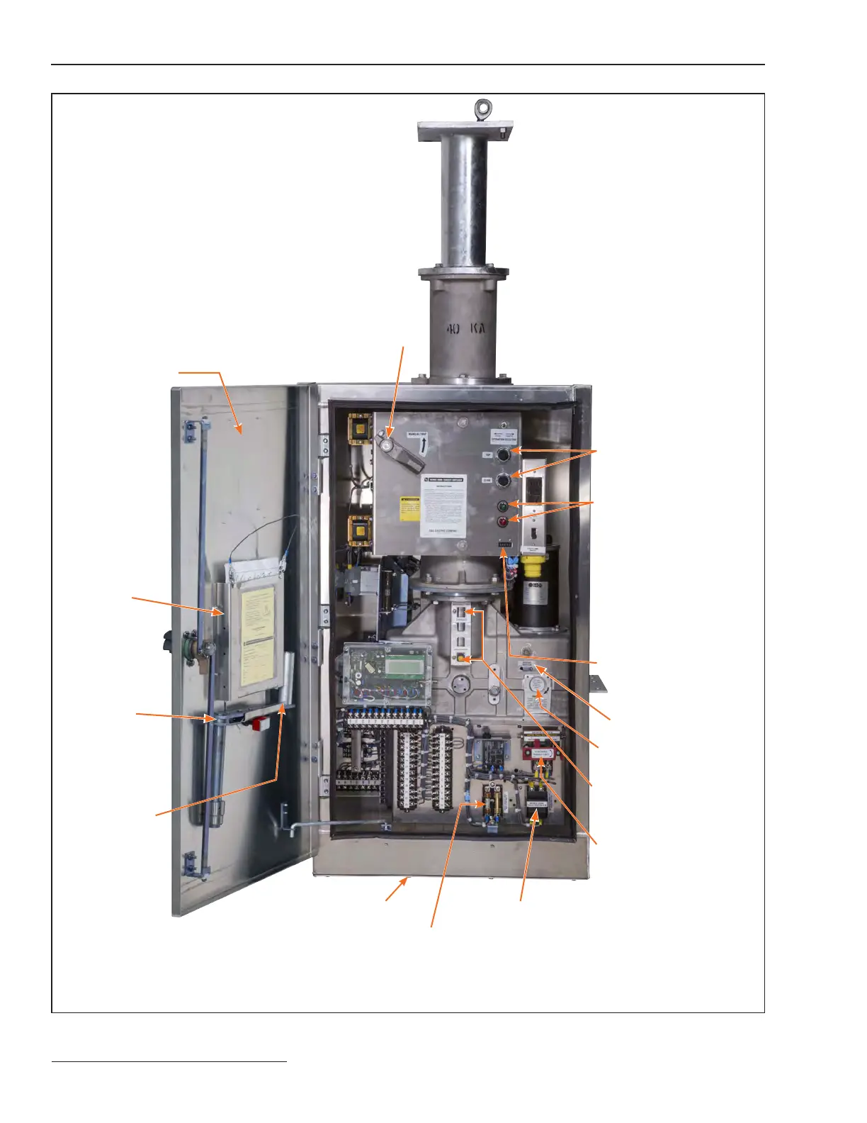
Figure 30. Interior of the switch operator.
“Trip” and “close”
pushbuttons
Position-indicating lamps
(Catalog Number Suffix “-M”)
Non-reset electric
operation counter
“Charged” and
“discharged” indicators for
stored-energy mechanism
Manual trip lever
Side access door for user’s external
connections (to terminal blocks at
bottom of enclosure)
Instruction
manual holder
Spare fuses
Manual charging
handle
Conduit entrance plate
Space-heater fuses
Motor-and-closing circuit fuseholder
Control-source knife
switch
Manual operating shaft
Access shutter
 Loading...


