Installation
10 S&C Instruction Sheet 716-500
Before Starting
CAUTION
Do not remove the containers from the interrupters or the
plastic bubble-wrap from the insulating support columns
until the installation is complete.
NOTICE
Bolted and Pinned Connections: A typical bolted con-
nection for field assembly requires one flat washer under
the cap screw and one under the nut. When self-locking
hex nuts are specified, it is essential that the threads of
the associated cap screws be lubricated with a general
purpose grease to facilitate tightening. All pins used in
the field assembly should also be lubricated to facilitate
insertion.
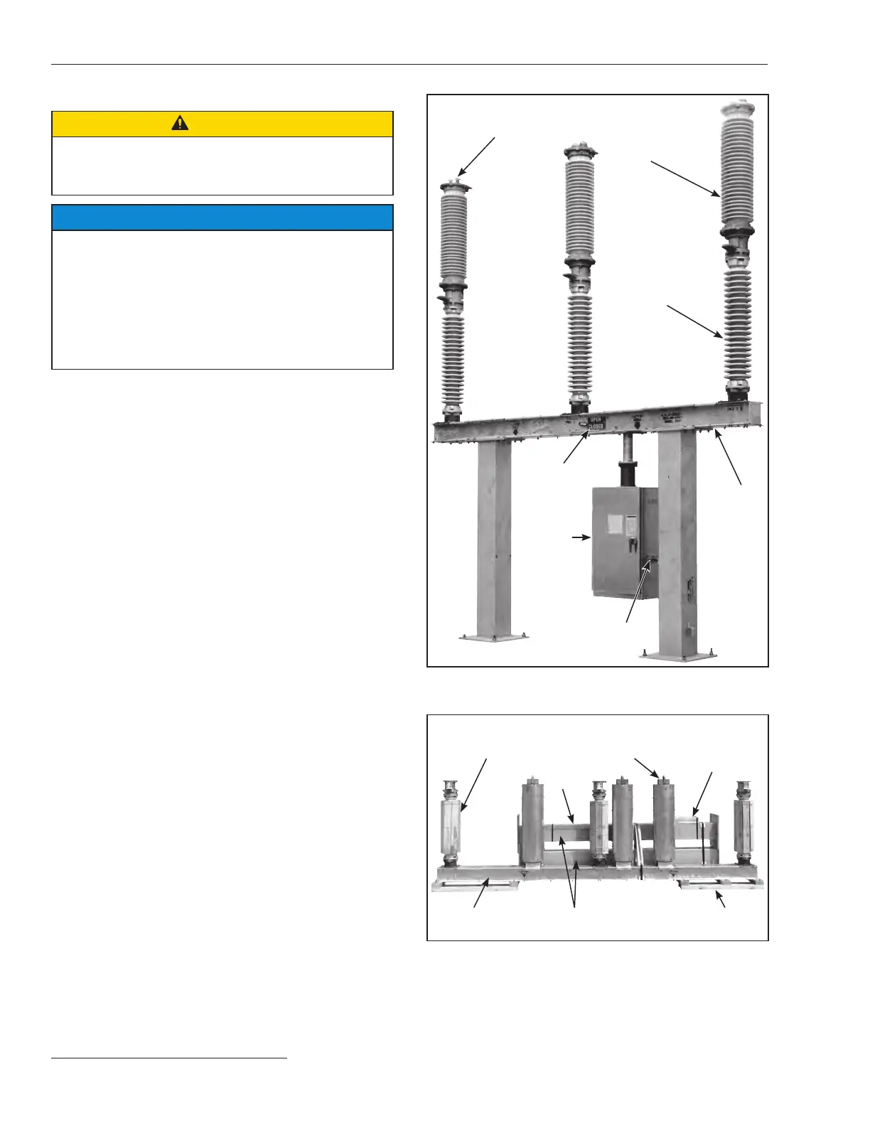
Pressure-relief device
and low-gas indicator
Interrupter
Insulating support
column
High-speed
base
(power train)
Operator support
plate
Operator
Switch position
indicator
Figure 1. Model 2030 Circuit-Switcher rated 138 kV.
Insulating
support
column
Lifting
angles
High-speed base Mounting pedestals
Interrupter
Operating
mechanism
components
and hardware
Shipping skid
Circuit-Switcher rated 69 kV though 138 kV
Figure 2a. Typical shipment of Model 2030 Series 2000 Circuit-
Switcher. Operator is shipped on a separate skid. (69-138 kV)