Installation
S&C Instruction Sheet 716-500 19
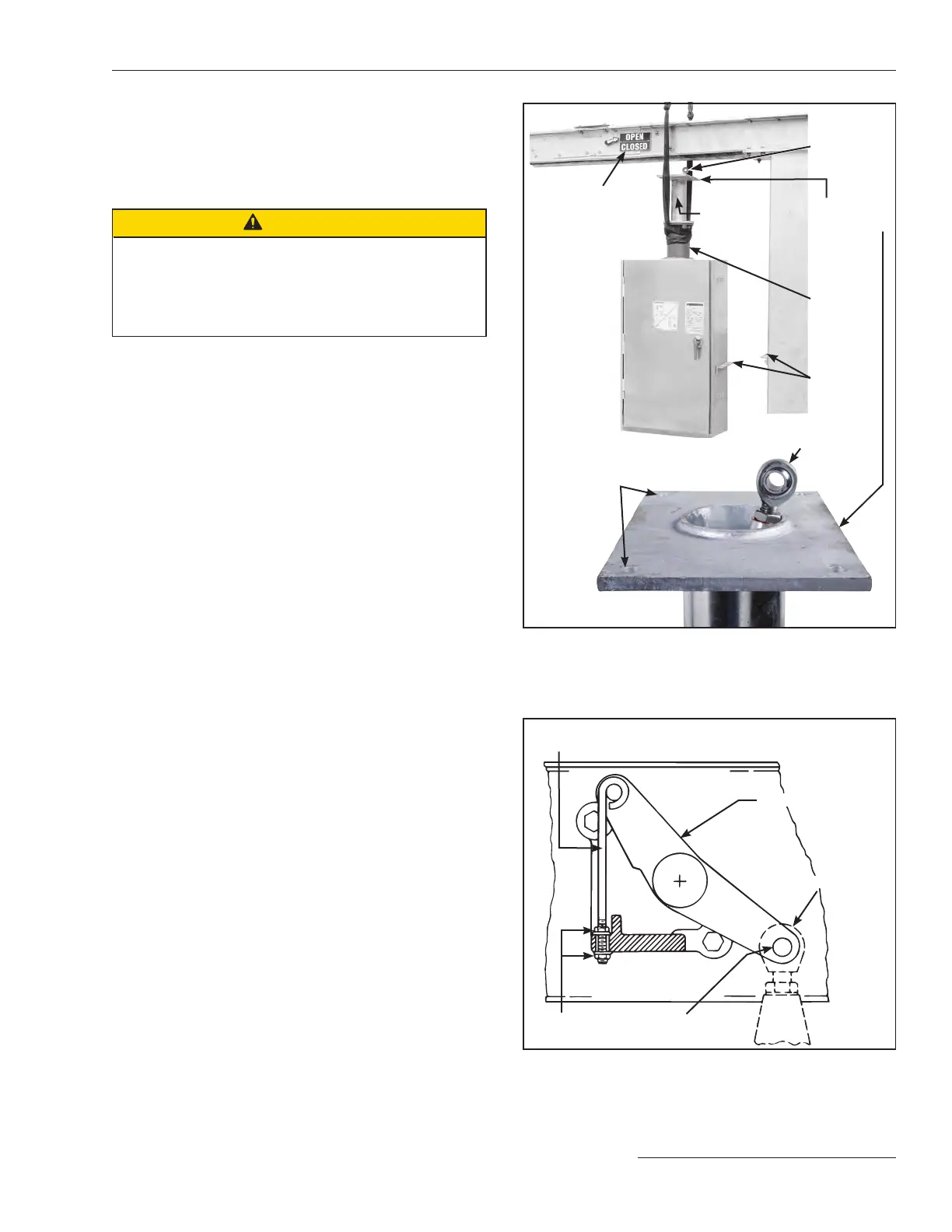
STEP 15. Reposition the lifting sling around the front of the
stored-energy housing and wrap another lifting
sling around the back of the stored-energy housing,
as shown in Figure 21. Face the operator door the
same direction as the Switch Position indicator on
the high-speed base. Hoist the operator into place.
CAUTION
Be careful not to damage the uni-ball coupling on the
operator-connecting link during hoisting and attachment
of the operator. The uni-ball coupling cannot be replaced
in the field. Damage will necessitate returning the opera-
tor for replacement.
Attach the operator support tube mounting plate to the
underside of the high-speed base using four ½-13 x 1¾ hex-
head galvanized steel cap screws, at washers, and self-
locking hex nuts. Lubricate the screws to facilitate tightening.
Tighten all four screws securely.
STEP 16. Attach the operator support angle to the appropri-
ate mounting pedestal using two ⅝-11 x 14 hex-head
galvanized steel cap screws, four at washers, and
two self-locking hex nuts. Refer to the catalog
drawing for exact placement. See Figure 21. Attach
the operator support plate to the angle on the
operator and the angle on the mounting pedestal
using four ½-13 x 1½ hex-head galvanized steel cap
screws, at washers, and self-locking nuts fur-
nished. Lubricate the bolts to facilitate tightening.
Securely tighten the screws. On circuit-switchers
with two or three mounting pedestals, insert the
hole plugs furnished into all unused holes in the
pedestals.
Uni-ball
coupling
Operator
support
tube
Stored-
energy
housing
Operator
support tube
mounting
plate
Holes (4) for ½ –132¾-inch hex-
head galvanized steel cap screws,
flat washers, and self-locking nuts
Uni-ball coupling
Operator
support
angles
Switch position
indicator
Figure 21. Hoist operator into position below the high-speed base
using a lifting crane.
Connecting the Operator to the High-Speed
Power Train
STEP 17. Attach the uni-ball coupling on the operator con-
necting link to the interphase drive lever in the
high-speed base using the ¾-inch stainless steel pin
and cotter pin retained from Step 7. See Figure 22.
An adjustable locking rod (marked with a black/
yellow striped label) is furnished, factory con-
nected to the interphase drive lever; turn the asso-
ciated ¼-20 locknuts as required to raise or lower
the interphase drive lever to facilitate insertion of
the stainless steel pin.
STEP 18. After the pin is installed, remove the lower ¼-20
locknut that retains the adjustable locking rod, and
then remove and discard the adjustable locking rod
and locknuts. See Figure 22.
Interphase drive lever
Adjustable locking rod (marked
with a black/yellow striped label)
¾-inch stainless steel
pin and cotter pin
Uni-ball coupling
¼-inch–20
locknut
Figure 22. Attach the uni-ball coupling on the operator-connecting
link to the interphase-drive lever inside the high-speed base.